® F230 Airless Sprayer Owner’s Manual • Betriebsanleitung • Manuel d'utilisateur Manual de usuario • Manuale dell'utente • Gebruikshandleiding Ejermanual • Användarmanual English Deutsch Français Español p. p. p. p. Italiano Nederlands Dansk Svenska p. p. p. p. 50 62 74 86 0106 © 2006 Wagner. All rights reserved. Form No. 0508296A Printed in the U. S. A.
The maximum operating range of the unit is 20.7 MPa (3000 PSI) fluid pressure. PREVENTION: • NEVER aim the gun at any part of the body. • NEVER allow any part of the body to touch the fluid stream. DO NOT allow body to touch a leak in the fluid hose. • NEVER put your hand in front of the gun. Gloves will not provide protection against an injection injury.
• Do not use materials with a flashpoint below 21° C (70° F). Flashpoint is the temperature at which a fluid can produce enough vapors to ignite. • Plastic can cause static sparks. Never hang plastic to enclose spray area. Do not use plastic drop cloths when spraying flammable materials. • Use lowest possible pressure to flush equipment. GAS ENGINE (WHERE APPLICABLE) Always place sprayer outside of structure in fresh air. Keep all solvents away from engine exhaust.
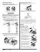
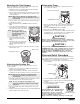
Attaching the Paint Hose Preparing to Paint 1. Attach the high pressure hose to the paint sprayer. Use a wrench to tighten the paint hose securely. Attaching the Tip to the Gun 1. Lock the trigger by rotating the trigger lock forward until it stops. Trigger locked (gun will not spray) 2. Attach the spray gun to the other end of the high pressure hose. Tighten the hose securely to the gun using two wrenches. Trigger unlocked (gun will spray) WARNING POSSIBLE INJECTION HAZARD.
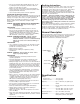
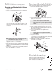
Mounting the Paint Hopper Priming the Pump Use the following procedure to mount the paint hopper and attach the return tube on a hopper unit. 1. Align the bottom of the paint hopper with the threaded inlet valve on the paint pump block. 2. Turn the paint hopper clockwise to thread it onto the inlet valve. Continue to turn the paint hopper until it is secure on the inlet valve. 1. Turn the pressure control knob counterclockwise to its lowest pressure setting.
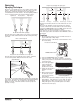
Spraying Proper way to trigger the spray gun Spraying Technique The key to a good paint job is an even coating over the entire surface. This is done by using even strokes. Keep your arm moving at a constant speed and keep the spray gun at a constant distance from the surface. The best spraying distance is 10 to 12 inches between the spray tip and the surface.
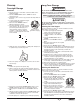
Long-Term Storage Cleanup Overnight Storage WARNING Shutdown Do not allow material to build up on the motor or the motor will overheat. Do not allow flammable solvents to come in contact with the motor or they could ignite. 1. Turn the pressure control knob counterclockwise to the minimum setting. 2. Turn the PRIME/SPRAY valve to PRIME to release system pressure. 3. Trigger the gun to remove any pressure that may still be in the hose. 4.
9. Turn the pressure control knob counterclockwise to the minimum setting. 10. Place the attached suction tube and return hose into the container of water or appropriate solvent. 11. Remove the spray tip and guard and place them into a container of the appropriate solvent. 12. Increase the pressure to 1/2 the maximum pressure. Let the water or solvent circulate for 2-3 minutes to flush paint out of the pump, the suction tube and the return hose. 6. Move the motor ON/OFF switch to ON. 7.
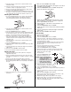
Maintenance Removing and Cleaning the Outlet Valve Follow these procedures when encountering problems indicated in the troubleshooting section. It may be necessary to remove and clean the outlet valve or to replace parts inside the valve worn out through normal use. 1. Remove the outlet valve body with a wrench. Removing and Cleaning the Inlet Valves 1. Perform the Pressure Relief Procedure, turn off and unplug the unit. 2. Remove the inlet valve assembly using a 27 millimeter socket or box end wrench.
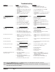
Troubleshooting Problem Cause The sprayer does not start up. The sprayer starts up but does not draw in paint when the PRIME/SPRAY valve is set to PRIME. Solution 1. The sprayer is not plugged in. 2. The ON/OFF switch is set to OFF. 3. Low or no voltage is coming from the wall plug. 4. The sprayer was turned off while still under pressure. 5. The extension cord is damaged or has too low a capacity. 6. The thermal overload on the sprayer is tripped. 7. There is a problem with the motor. 1.
Main Assembly — Suction Set Unit Parts Listing Main Assembly — Hopper Unit 1 1 8 9 2 10 2 3 5 3 11 4 4 6 12 5 7 6 13 8 Item 1 2 3 4 5 6 7 8 Part # 0288144 ---------0555126 0311200 0278310 9811122 0294635 0270343 9805213 14 Description Quantity Hopper assembly..................................1 Pump head assembly ...........................1 Diaphragm pump, 220–240 VAC..........1 Diapragm pump, 100–120 VAC Stand ....................................................1 Lock nut .....................
Diaphragm Pump (P/N 0555126 / 220–240 VAC or P/N 0311200 / 100–120 VAC) 19 20 1 21 2 3 4 5 6 7 8 9 22 23 10 11 12 24 25 13 14 26 15 16 AS-3112 BS-546 CEE 7/7 NEMA 5-15P 0270 405 220V~240V 0508111 110V~120V 9952995 220V~240V 0275503 100V 13 17 18 Item 1 2 3 4 5 6 7 8 9 10 11 12 13 14 15 16 17 Part # 0311215 0270494 0270201 9801109 0288775 0270529 0047373 0089518 0089475 0278345 0005311 0270550 0047393 0278359 0278341 9800049 0090031 R Description Quantity Pump head ......................
Hopper Assembly Pump Head Assembly 1 1 2 12 2 13 3 14 3 15 7 16 4 4 6 5 6 7 8 5 9 10 11 Item 1 2 3 4 5 6 7 8 9 10 11 12 13 14 15 16 Item 1 2 Part # 0278242 0089482 0278334 0555901 0278362 0278241 0093635 0047485 0278361 9871114 0278335 0278337 0278250 0278368 0156646 0278340 Description Quantity Inlet valve assembly (includes item 2)........1 Sealing washer, nylon.................................1 Paint pump..................................................1 PRIME/SPRAY valve assembly......