GB ® Operating manual ProSpray 3.29 • 3.31 Airless high-pressure spraying unit Models: 0558014 0558015 0558016 0558029 0558299 0558387 0558388 Original operating manual ProSpray 3.29 • 3.
GB Warning! Attention: Danger of injury by injection! Airless units develop extremely high spraying pressures. 1 Never put your fingers, hands or any other parts of the body into the spray jet! Never point the spray gun at yourself, other persons or animals. Never use the spray gun without safety guard. Do not treat a spraying injury as a harmless cut. In case of injury to the skin through coating materials or solvents, consult a doctor immediately for quick and expert treatment.
GB Contents Safety regulations for Airless spraying........................ 4 Earthing instructions.........................................................5 2. 2.1 2.2 General view of application...........................................6 Application........................................................................6 Coating materials..............................................................6 3. 3.1 3.2 3.3 Description of unit..........................................................
Safety Regulations 1. GB Safety regulations for Airless spraying This manual contains information that must be read and understood before using the equipment. When you come to an area that has one of the following symbols, pay particular attention and make certain to heed the safeguard. NOTE TO PHYSICIAN: Injection into the skin is a traumatic injury. It is important to treat the injury as soon as possible. DO NOT delay treatment to research toxicity.
Safety regulations GB General view of application HAZARD: HAZARDOUS VAPORS Paints, solvents, insecticides, and other materials can be harmful if inhaled or come in contact with body. Vapors can cause severe nausea, fainting, or poisoning. HAZARD: EXPLOSION HAZARD DUE TO INCOMPATIBLE MATERIALS Will cause severe injury or property damage. PREVENTION: • Do not use materials containing bleach or chlorine. • Do not use halogenated hydrocarbon solvents such as methylene chloride and 1,1,1 - trichloroethane.
General view of application 2. GB Description of unit General view of application 2.1 Application = Recommended = Not-recommended recommended nozzle size: FineFinish 0.008“ - 0.014“ Emulsion paints, latex paints recommended nozzle size: 0.017“ - 0.027“ Anti-corrosive agents, flame retardants, fabric adhesive recommended nozzle size: 0.021“ - 0.031“ Airless-scrapers recommended nozzle size: 0.027“ - 0.039“ 2.2 PS 3.
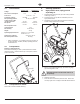
GB 3.3 1 2 3 4 5 6 7 8 Description of unit Legend for explanatory diagram ProSpray 3.29 / 3.31 Spray gun High-pressure hose Oil cup for EasyGlide (EasyGlide prevents increased wear of the packings) Oil level gauge Pail hook Oil button Suction tube Return hose 3.
GB Description of unit 3.5 4. Technical data ProSpray 3.29 ProSpray 3.31 Voltage: 220~240 Volt, 50/60 Hz Max. current consumption: 7.5 A Power cord: 4.1 8A 3 x 1.5 mm2 Max tip size: 3,0 l/min 0.029 inch – 0.73 mm Max. temperature of the coating material: High-pressure hose, spray gun and separating oil 3,8 l/min 0.032 inch – 0.81 mm 43°C Max viscosity: Weight: Special high-pressure hose: Starting operation 1.
GB Solid Green When the pressure indicator is solid green, the sprayer is operating between 12 MPa (120 bar) and 23 MPa (230 bar). A solid green pressure indicator means: • The sprayer is at the proper pressure setting for spraying oil-based and latex house paints • The sprayer is operating at peak performance at a high pressure setting • If the pressure indicator goes to solid yellow when the pressure is set so that it starts at solid green, it indicates one of the following: a.
GB Starting operation 4.5 Cleaning preserving agent when startingup of operation initially 4.7 The Digital Electronic Spray Control (DESC) increases the functionality of the sprayer. It is installed directly below the pressure control knob on the control panel. It consists of a display and four function keys. The display shows various menu screens that allow the user to customize and monitor sprayer operation using the function keys. 1. Immerse the suction tube (Fig.
GB Security Code Screen SECURITY CODE The Security Code screen allows the MENU-1 CHANGE-2 user to set a four digit security code to prevent unauthorized use of the sprayer. If a security code has been set, the control system display will ask for the code at startup. If the correct code is entered, the display will show the Main Screen and the sprayer will operate. If the wrong code is entered, the display will continue to ask for the correct code and the sprayer will be disabled.
GB Spraying technique 5. Spraying technique Handling the high-pressure hose 6. Handling the high-pressure hose Avoid sharp bending or kinking of the high-pressure hose. The smallest bending radius amounts to about 20 cm. Do not drive over the high-pressure hose. Protect against sharp objects and edges. Injection hazard. Do not spray without the tip guard in place. NEVER trigger the gun unless the tip is completely turned to either the spray or the unclog position.
GB 8. Cleaning the unit (shutting down) 8.1 A clean state is the best method of ensuring operation without problems. After you have finished spraying, clean the unit. Under no circumstances may any remaining coating material dry and harden in the unit. The cleaning agent used for cleaning (only with an ignition point above 21 °C) must be suitable for the coating material used. • Secure the spray gun, refer to the operating manual of the spray gun. Clean and remove tip.
GB Cleaning the unit (shutting down) 8.3 1. 2. 3. Cleaning Airless spray gun Remedy in case of faults Assembly 1. Place intake filter (3) with the long cone into the gun housing. 2. Screw in grip (2) into the gun housing and tighten. 3. Slot in protective guard (1). Rinse Airless spray gun with an appropriate cleaning agent. Clean tip thoroughly with appropriate cleaning agent so that no coating material residue remains. Thoroughly clean the outside of the Airless spray gun.
GB Type of malfunction D. E. F. G. Remedy in case of faults Possible cause Measures for eliminating the malfunction Coating material exits at the top of the fluid section 1. Upper packing is worn. 1. Remove and replace packing. 2. Piston is worn. 2. Remove and replace piston. Increased pulsation at the spray gun 1. Incorrect high-pressure hose type. 1. Only use WAGNER original-high-pressure hoses in order to ensure functionality, safety and durability. 2. Tip worn or too large. 2.
GB Servicing 10. 10.1 Servicing 11.2 Danger of crushing - do not reach with the fingers or tool between the moving parts. 2. Turn the pressure control knob to minimum pressure. The DESC screen should say “PRIME”. 3. Press the #1 key on the DESC control panel. The “CREEP MODE” screen will now appear. 4. Slowly turn the pressure control knob clockwise to increase the pressure. The crankshaft/slider assembly will begin to move very slowly. 5.
GB Repairs at the unit 8. Push piston (4) downward out of the upper housing (6). Check piston for wear and replace if necessary. 9. Remove upper packing (8) and lower packing (9) from the upper housing (6). 14. Unscrew lower housing (Fig. 13, Item 10) with adjusting wrench while holding the upper housing (11) securely with a second adjusting wrench. 15. Remove bearing ring (13) and O-ring (12). 16. Screw out outlet valve housing (14) from the piston (15) with 3/8 inch hexagon socket head wrench. 17.
GB Repairs at the unit 12. 18. Lubricate installation tool and piston (4) with machine grease. 19. Push piston (4) through the lower and upper packings until the upper end of the piston protrudes from the threaded joint (7). 20. Remove installation tool from piston (4). 21. Slide the top of the piston (4) into the T-slot (2) on the slider assembly (3). 22. Screw lock nut (5) at the upper housing (6) until it touches. 23. Lubricate the threading of the upper housing (6) with machine grease.
GB 12. 12.1 Appendix Appendix Selection of tip To achieve faultless and rational working, the selection of the tip is of the greatest importance. In many cases the correct tip can only be determined by means of a spraying test. Some rules for this: The spray jet must be even. If streaks appear in the spray jet the spraying pressure is either too low or the viscosity of the coating material to high. Remedy: Increase pressure or dilute coating material.
GB Appendix 12.4 Airless tip table WAGNER Trade Tip 2 up to 270 bar (27 MPa) without tip F thread (11/16 - 16 UN) for Wagner spray guns Order no. 0556 042 Application Natural paints Clear paints Oils Tip marking Spray angle without tip G thread (7/8 - 14 UN) for Graco/Titan spray guns Order no. 0556 041 Bore inch / mm Spraying width mm 1) Order no. Spray gun filter “green” Spray gun filter “white” Spray gun filter “yellow” Spray gun filter “RED” 407 40° 0.007 / 0.
GB 12.5 Appendix TempSpray The paint material is heated to the required temperature uniformly by an electric heating element, which is located inside the hose (regulated from 20°C to 60°C). Advantages: • Constant paint temperature even at low outside temperatures • Considerably better working of high viscosity coating materials • Increased application efficiency • Savings in solvents due to reduction in viscosity • Adaptable to all airless units Order No.
GB Appendix 12.6 Pump-Runner (Order No. 2306987) Universal accessories for cleaning, clean transportation and preservation of the pump unit.
ProSpray 3.29 • 3.31 Deutschland J. Wagner GmbH • Otto-Lilienthal-Straße 18 • 88677 Markdorf Tel. 0043/07544/5050 • Fax: 0043/07544/505/200 • info@wagner-group.com Österreich J. Wagner Ges.m.b.H • Ottogasse 2/20 • 2333 Leopoldsdorf Schweiz J. Wagner AG • Industriestrasse 22 • 9450 Altstätten Tel. 0041/71/7572211 • Fax: 0041/71/7572222 • wagner@wagner-group.ch Japan Wagner Spraytech Japan/Ltd. • 2-35, Shinden-Nishimachi • Osaka/Japan Tel.
Accessories illustration ProSpray 3.29 / 3.31 2 1 5 3 4 6 8 24 7 ProSpray 3.29 • 3.
Item Part No. Description 1 0296 388 Spray gun AG 08, F-thread 0296 386 Spray gun AG 08, G-thread 0502 166 Spray gun AG 14, F-thread 0502 119 Spray gun AG 14, G-thread 0296 441 Pole gun 120 cm, G-thread 7/8” 0296 443 Pole gun 120 cm, F-thread 11/16” 0296 442 Pole gun 200 cm, G-thread 7/8” 0296 444 Pole gun 200 cm, F-thread 11/16” 3 0345 010 In-line roller IR-100 4 9984 573 High-pressure hose DN 4 mm, 7.
Spare parts list ProSpray 3.29 / 3.31 Main Assembly 44 46 45 47 1 48 49 11 12 13 2 50 14 51 15 3 16 18 17 4 5 19 2 6 31 20 21 22 32 23 7 24 33 25 8 26 28 9 27 52 10 29 30 34 35 36 37 38 39 40 41 42 43 26 ProSpray 3.29 • 3.
Item Part No. Description Item Part No.
Spare parts list ProSpray 3.29 / 3.31 Fluid section 1 2 3 4 5 6 7 8 9 10 11 12 24 13 14 15 16 17 18 19 20 21 22 9 10 23 28 ProSpray 3.29 • 3.
Item Part No.
Spare parts list ProSpray 3.29 / 3.31 Drive Assembly 3 1 4 5 6 7 8 2 9 10 11 12 13 Item Part No. Description 1 0558 323A 2 0290 241 Slider assembly 3 0290 254 Thrust washer 4 0290 239 Gear/crankshaft assembly 5 0290 240 1st stage gear 6 0558 324A 7 0508 559 Screw (6) 8 0290 261 Baffle assembly 9 0509 218 Screw (4) 10 0558 535 Electronic control assembly (PS 3.29) 0558 536 Electronic control assembly (PS 3.
Spare parts list ProSpray 3.29 / 3.31 Filter assembly 1 2 3 4 5 6 7 8 9 10 11 12 14 13 Item Part No.
Spare parts list ProSpray 3.29 / 3.31 Upright cart assembly 1 7 8 2 3 9 4 10 5 11 6 12 11 13 14 Item Part No.
Spare parts list ProSpray 3.29 Low boy cart assembly 1 10 2 11 12 13 3 14 4 5 15 6 7 8 9 Item Part No. Description 1 0290 290 Cart 2 0508 381 Drip cup 3 0290 291 Wheel 4 0294 534 Wheel spacer 5 9890 104 Axle cap 6 9805 230 Drip cup screw 7 0509 386 Washer 8 0295 608 Screw 9 9885 571 Plug 10 0294 635 Plug 11 0295 609 Washer 12 0295 607 Handle sleeve 13 9841 504 Spring button 14 0295 610 Roll pin 15 0290 292 Handle assembly ProSpray 3.29 • 3.
Spare parts list ProSpray 3.29 Suction system for low boy cart 1 3 4 2 Item Part No. Description 1 0507 964 Return hose 2 0507 965 Siphon tube 3 5006 536 Inlet screen 4 0507 783 Clamp 5 0507 967 Siphon tube adapter ------- Tie wrap (not shown) 5 34 ProSpray 3.29 • 3.
GB Important notes on product liability As a result of an EC regulation being effective as from January 1, 1990, the manufacturer shall only be liable for his product if all parts come from him or are released by him, and if the devices are properly mounted and operated.
Note on disposal: In observance of the European Directive 2002/96/ EC on waste electrical and electronic equipment and implementation in accordance with national law, this product is not to be disposed of together with household waste material but must be recycled in an environmentally friendly way! Wagner or one of our dealers will take back your used Wagner waste electrical or electronic equipment and will dispose of it for you in an environmentally friendly way.