Betriebsanleitung Operating manual ................. p. 24 Mode d’emploi ...................... p. 48 Istruzioni per l’uso ................ p.
g Warning! Attention: Danger of injury by injection! Airless units develop extremely high spraying pressures. Danger ① ② Never put your fingers, hands or any other parts of the body into the spray jet! Never point the spray gun at yourself, other persons or animals. Never use the spray gun without safety guard. Do not treat a spraying injury as a harmless cut. In case of injury to the skin through coating materials or solvents, consult a doctor immediately for quick and expert treatment.
g Contents Contents Page Page 1. Safety regulations for Airless spraying. . . 26/27 2. General view of application . . . . . . . . . . . . 27/28 2.1 Application . . . . . . . . . . . . . . . . . . . . . . . . . . 27 2.2 Coating materials . . . . . . . . . . . . . . . . . . . . . 28 3. Description of unit . . . . . . . . . . . . . . . . . . . 28-31 3.1 Airless process . . . . . . . . . . . . . . . . . . . . . . . 28 3.2 Functioning of the unit . . . . . . . . . . . . . . . . . 28 3.
g Safety regulations 1. Safety regulations for Airless spraying All local regulations in force must be observed. For secure handling of Airless high-pressure spraying units the following safety regulations are to be observed: Flash point Only use coating materials with a flash point of 21 °C or above without additional heating. The flash point is the lowest temperature Danger at which vapours develop from the coating material.
g Safety regulations For reasons of function, safety and durability use only original WAGNER high-pressure hoses. i Electrostatic charging (formation of sparks or flame) Under certain circumstances, electrostatic charging can occur on the unit due to the rate of flow of the coating material when spraying. On discharging this can result in Danger the emergence of sparks or fire. It is therefore necessary that the unit is always earthed through the electrical installation.
g Description of unit 2.2 Coating materials Processible coating materials Pay attention to the Airless quality of the coating materials to be processed. i Dilutable lacquers and paints or those containing solvents, two-component coating materials, dispersions, latex paints, façade paints, roof and attic coatings, fire and corrosion protection material. No other materials should be used for spraying without WAGNER’s approval.
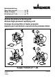
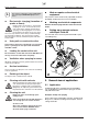
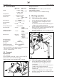
g Description of unit 3.3 Explanatory diagram 3.3.1 Super Finish 21 – Vertical set-up with suction system 1 2 1 2 3 4 4 3 5 6 16 5 15 14 13 6 7 8 9 10 11 12 7 8 9 12 11 10 13 14 15 16 Spray gun High-pressure hose Outlet valve Socket, max. load 1000 Watt (230 Volt~, 50 Hz, 220 Volt~, 60 Hz) Socket, max.
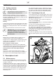
g Description of unit 3.3.3 Super Finish 23 – Vertical set-up with suction system 19 1 2 18 1 2 3 4 5 6 4 3 17 7 8 9 10 11 16 15 5 12 14 6 7 13 8 9 12 11 10 13 14 15 16 17 18 19 Spray gun High-pressure hose Outlet valve Socket, max.
g Description of unit 3.4 Starting operation Technical data Voltage Super Finish Super Finish 21 23 : 230 Volt~, 50 Hz 220 Volt~,60 Hz 110 Volt~, 50 Hz Fuse protection : 16 A slow-blow Unit connection line : 6 m long, 3 x 1.5 mm2 Socket on unit : 230 Volt ~, 50 Hz 220 Volt~, 60 Hz 110 Volt~, 50 Hz Max. connection : 1000 Watt 400 Watt (110 Volt~, 50 Hz) Type of protection : IP 44 Capacity : 0.96 kW Max. operating pressure : Max. volume flow : 2.0 l/min 2.4 l/min 3.
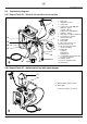
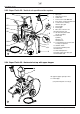
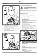
g Starting operation 4.4 Connection to the mains The connection must take place through a correctly earthed two-pole and-earth socket outlet. Attention 5 3 2 6 Before connection to the mains, pay attention to the fact that the mains voltage agrees with the information on the makers’ name plate on the rear of the unit. The green control lamp will light up as soon as the mains plug has been connected. 4 4.5 Cleaning preserving agent when starting-up of operation initially 1.
g Starting operation Spraying technique 4.8 Socket on unit It is possible, for example, to connect an agitator, a working lamp etc with a maximum of 1000 Watt (230 Volt~, 50 Hz, 220 Volt~, 60 Hz), 400 Watt (110 Volt~, 50 Hz) 2 Completely unroll a connected cable drum. 1 Attention 4.
g Interruption of work Cleaning unit (shutting down operation) 7. Interruption of work 6. 1. 7. 2. 3. 4. 5. 6. Open the relief valve, valve position k (circulation). Switch off the unit. Pull trigger guard of spray gun to decrease the pressure of the highpressure hose and the spray gun. Secure spray gun, see operating manual for spray gun. If the tip is to be cleaned, see page 46, point 13.2.
g Cleaning unit (shutting down operation) 1. 2. 3. 4. Cleaning unit from outside Unit with suction system Unit with upper hopper Switch on the unit. Turn pressure regulatin knob to the right. Close the relief valve, valve position p (spraying). Pull the trigger guard on the spray gun in order to pump residue coating material from the upper hopper, the high-pressure hose and the spray gun into an open container. – Screw off the filter (fig. 15) from suction pipe. – Clean or replace the filter.
g Cleaning Airless spray gun G 12 Remedy in case of disturbance Intake filter in Airless spray gun 1 2 3 4 5 8.4 Dismounting (fig. 18) 1. Pull protective guard (1) forward vigorously. 2. Screw grip (2) out of the gun housing. Remove intake filter (3). 3. Intake filter congested or defective – replace. Mounting 1. Place intake filter (3) with the long cone into the gun housing. 2. Screw in grip (2) into the gun housing and tighten. 3. Slot in protective guard (1).
g Remedy in case of disturbance Type of malfunction Possible cause Measure for elimination of malfunction Unit does not exert suction Inlet valve is clogged, cannot be pressed down into inlet valve housing. Switch off unit. Inlet valve must allow movement; test by pressing the inlet valve slightly with a soft implement (e.g. a pencil). Moving the inlet valve back and forth removes impurities from the valve seat.
g Servicing Repairs on the unit 10. Servicing 10.1 General servicing Servicing of the unit should be carried out once annually by the WAGNER service. 1. Check high-pressure hoses, unit connection line, plug and socket for damage. 2. Check inlet valve, outlet valve, diaphragm and filter for wear. 3. Check oil level (fig. 19) in the horizontal set-up. 4. Remove clasp (3) by means of a screwdriver. 5. Place accompanying spanner 30 mm on the inlet valve (2). Withdraw carefully turning the inlet valve. 6.
g Repairs on the unit 11.2 Outlet valve (fig. 21) 1. Screw out outlet valve with spanner 22 mm from the paint section. Attention 2. Remove clasp (1) carefully with screwdriver, pressure spring (2) presses parts out 3 to 4. 3. Clean or replace individual parts. 4. Check O-ring (6) for damage. 5. Pay attention to installation position in mounting spring support ring (3), outlet valve seat (4) and seal ring (5). 1 11.4 Relief valve (fig. 23) 1 3 4 5 Danger 6 2 Switch off unit.
g Repairs on the unit 11.5 Exchanging diaphragm (fig. 24) Danger 11.6 Replace unit connection line (fig. 25) Switch off unit. Pull mains plug from socket before repair. Danger 1. Unscrew both screws (1) from the hood (2). 2. Screw hexagonal screws (3) from the flange ring (4) with spanner 19 mm. 3. Remove paint section (5). 4. Remove insert (6) and diaphragm (7). 5. The diaphragm can only be used once. Always replace diaphragm.
g Repairs on the unit 11.
g Accessories and spare parts 12. Accessories and spare parts 12.1 Accessories for Super Finish 21 and 23 (accessories illustration, see page 96) Item 1 2 3 4 5 6 7 8 9 10 11 12 13 14 15 16 Super Finish 21 Super Finish 23 Order no. Order no.
g Accessories and spare parts 12.5 Spare parts diagram trolley Super Finish 23 12.2 Spare parts list frame Super Finish 21 Item Order no. Description 1 2 3 4 5 6 0344 330 9990 867 3050 347 9900 407 9905 309 0340 303 Frame Rubber foot Disk 6,4 Screw M 6 x 40 Cylinder head screw M 6 x 45 Foot 6 1 2 7 5 4 5 12.3 Spare parts diagram frame Super Finish 21 8 9 3 1 12.6 Spare parts list suction system 6 Item Order no.
g Accessories and spare parts 12.8 Spare parts list upper hopper, 5 litres (spare parts diagram, see page 98) 12.9 Spare parts list upper hopper, 20 litres (spare parts diagram, see page 98) Item Order no. Description 1 2 0341 265 0340 901 9902 306 3 4 5 0037 607 0340 904 0340 908 Upper hopper fittings, 5 litres Cover Combination sheet metal screw 3.9 x 13 Filter disk, mesh width 0.8 mm Upper hopper Return pipe Item Order no.
Super Finish 21 • 23 0344 205 9905 111 9905 112 ––––––– 9950 241 9950 242 0340 302 0340 353 ––––––– 0340 352 ––––––– 0341 706 3056 464 9970 532 0341 324 9960 151 9922 518 9960 431 9922 506 9960 432 9900 315 9920 806 0344 210 9993 105 0341 445 0288 317 0288 309 0341 446 0341 307 0341 309 3050 858 9906 007 0341 348 9971 146 0341 349 0340 490 9903 317 Super Finish 21 Order no.
g Appendix 13. Appendix 13.1 Selection of tip To achieve faultless and rational working, the selection of the tip is of the greatest importance. In many cases the correct tip can only be determined by means of a spraying test. Some rules for this: The spray jet must be even. If streaks appear in the spray jet the spraying pressure is either too low or the viscosity of the coating material to high. Remedy: Increase pressure or dilute coating material.
g Appendix WAGNER tip up to 530 bar (53 MPa) without tip F thread (11/16 - 16 UN) for Wagner spray guns Order no. 1006 001 without tip G thread (7/8 - 14 UN) for Graco/Titan spray guns Order no. 1006 002 without tip Order no. 1088 001 62 1 1 62 13.4 Airless tip table WAGNER Professional tip up to 270 bar (27 MPa) Standard tips up to 530 bar (53 MPa) Application Tip marking Spray angle Bore inch / mm Spraying width mm 1) Order no. Order no. Order no.
d Zubehörbild g Accessories illustration i Figura degli accessori f Illustration des accessoires Super Finish 21 • 23 3 2 1 6 4 9 10 5 8 7 VAW max.
Ersatzteilbild Spare parts diagram Schema pezzi di ricambio Illustration des pièces de rechange 1 Super Finish 21 • 23 d Pumpenkopf 45 g Pump head f Tête de pompe i Testa della 2 44 5 3 30 6 pompa 5 31 7 43 34 32 37 8 39 12 13 36 35 33 14 28 29 21 16 15 17 18 19 20 22 23 24 SF 21 • 23 / 05 / 02 Super Finish 21 • 23 97
Ersatzteilbild Spare parts diagram Schema pezzi di ricambio d g f i Illustration des pièces de rechange d g f i Oberbehälter 5 Liter Upper hopper, 5 litres Cuve de gravité 5 litres Contenitore superiore da 5 litri Oberbehälter 20 Liter Upper hopper, 20 litres Cuve de gravité 20 litres Contenitore superiore da 20 litri 3 1 5 6 7 9 10 2 3 5 4 1 2 15 16 17 13 18 98 Super Finish 21 • 23
Ersatzteilbild Spare parts diagram Schema pezzi di ricambio Illustration des pièces de rechange Super Finish 21 • 23 d Pumpen-Aggregat f Groupe de pompe 55 64 SF 21 • 23 / 09 / 01 42 65 10 9 25 16 17 Super Finish 21 • 23 1 2 3 2 4 14 15 5 13 18 19 24 20 21 8 36 37 38 26 29 30 32 27 31 33 28 66 39 34 35 40 1 41 3 43 48 44 54 45 58 60 61 59 62 63 46 53 47 52 50 51 g Pump aggregate i Aggregato pompe 99
Servicenetz in Deutschland Hamburg J. Wagner GmbH Service-Stützpunkt Hamburg Oehleckerring 9a - 13 22419 Hamburg Tel. 040 / 5314010 Telefax 040 / 5324618 Dresden J. Wagner GmbH Service-Stützpunkt Dresden Joachim Walther Neuhausener Straße 5 09548 Deutscheinsiedel Tel. 03 73 62 / 82 63 Telefax 03 73 62 / 1 72 20 Hannover J. Wagner GmbH Service-Stützpunkt Hannover Evered J. Poole Schmiedestraße 7 30938 Burgwedel/Wettmar Tel. 0 51 39 / 89 26 89 Telefax 0 51 39 / 8923 97 Mobil 0171 / 3519988 Münster J.
d Prüfung des Gerätes nach den Richtlinien für Flüssigkeitsstrahler (Spritzgeräte) der Berufsgenossenschaften. Das Gerät ist bei Bedarf, jedoch mindestens alle 12 Monate, durch Sachkundige daraufhin zu prüfen, ob ein sicherer Betrieb weiterhin gewährleistet ist. Bei stillgelegtem Gerät kann die Prüfung bis zur nächsten Inbetriebnahme hinausgeschoben werden. Der Betreiber ist verpflichtet, das Gerät zur Prüfung anzumelden. Wenden Sie sich bitte an die Kundendienststellen der Firma WAGNER.
d f Déclaration de conformité Konformitätserklärung Hiermit erklären wir, dass die Bauart von WAGNER Super Finish 21, 230 V, 50 Hz WAGNER Super Finish 23, 230 V, 50 Hz folgenden einschlägigen Bestimmungen entspricht: 73/23 EWG, 89/336 EWG und 89/392 EWG. Angewendete harmonisierte Normen, insbesondere: EN 292-1/-2, EN 55014, EN 55104, EN 60204-1, EN 6100-3-2 Angewendete nationale technische Spezifikationen, insbesondere: VBG 5, BGV D15 Datum: 18. 12.