
Datasheet


2
211
2
<
2,1
>
1,2
2,2
<____
>
L
<___ ___>
4
< >
<_
<
6,1
_>
14
<__________ _______>
6
<_ _>
3,5
<
>
4
<
2
<
>
>
0,4
<___
>
0,4
<
___>
>
0,95
<___
<__
)
4
( )
<_______ _______>
12,7
<_____ ____>
11,1
<____ ____>
4
<>
4,5
< >
13,1
0,4
___>
<
>
<
___>
<__
24
>
<
>
<
<
>
__>
A
0,3
5,3
10,8
14,8
R
<_
<
2,1
>
1,2
2,2
<____
>
L
<___ ___>
4
< >
<_
<
6,1
_>
14
<__________ _______>
6
<_ _>
3,5
<
>
4
<
2
<
>
>
0,4
<___
>
0,4
<
___>
>
0,95
<___
<__
)
4
( )
<_______ _______>
12,7
<_____ ____>
11,1
<____ ____>
4
<>
4,5
< >
13,1
0,4
___>
SMD PCB Terminal Blocks with Push-Buttons, 0.75 mm
2
Pole
No.
Item No. Pack. Unit
Pole
No.
Item No. Pack. Unit
SMD PCB terminal block with push-buttons
in tape-and-reel packaging, white*
SMD PCB terminal blocks with push-buttons
in tape-and-reel packaging, black
1
2060-451/998-404
13500 (9 x 1500) 1
2060-471/998-404
13500 (9 x 1500)
2
2060-452/998-404
9000 (9 x 1000) 2
2060-472/998-404
9000 (9 x 1000)
3
2060-453/998-404
6750 (9 x 750) 3
2060-473/998-404
6750 (9 x 750)
Reel diameter: 330 mm Reel diameter: 330 mm
Pin spacing: 4 mm / 0.157 in . Pin spacing: 4 mm / 0.157 in .
0.2 … 0.75 mm
2
24 … 18 AWG
0.2 … 0.75 mm
2
24 … 18 AWG
160 V/2.5 kV/2 9 A 160 V/2.5 kV/2 9 A
Inserting solid conductors via push-in termination. Inserting/removing fi ne-stranded conductors by
lightly pressing on push-button (e.g., using a 206-
860 operating tool).
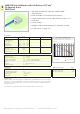
L = (pole no. x pin spacing) – 0.1 mm L = (pole no. x pin spacing) – 0.1 mm
PCB terminal blocks can be arranged side-by-side with-
out loss of poles.
R = Feed direction
A = (pole no. x pin spacing) + 4 mm
* Depending on refl ow soldering temperatures and times, color deviations may occur.
These deviations will have no impact on functionality.