
Datasheet
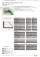
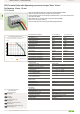

10 20 30 40 50 60 70 80 90 100105
0
20
30
40
10
2-, 4-, 6-
Current-Carrying Capacity Curve
Pin spacing: 7.5 mm / Conductor cross-section: 6 mm² "f-st"
Based on: EN 60512-5-2 / Reduction factor: 1
Current in A
Ambient operating temperature in °C
Conductor rated currentpole
Volume 2, Section 1 | PCB Terminal Blocks www.wago.com
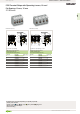
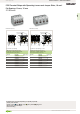
PCB Terminal Blocks and Connectors
PCB Terminal Strips with Operating Levers, 16 mm²
Pin Spacing: 10 mm, 15 mm
2716 Series
• High-current PCB terminal strips with lever-actuated CAGE CLAMP®
• Tool-free opening and closing – fingers open/close levers
• Several clamping units can be held open simultaneously – convenient for terminat-
ing multi-core cables
• Four solder pins per contact point for high mechanical stability
• 600 V UL for 15 mm pin spacing
• Pin and dimensions compatible to high-current, screw-type terminal blocks
Marking accessories,
see page 604
Test plugs,
see page 601
Additional technical information,
see Section 13
Approvals and corresponding ratings,
visit www.wago.com
Electrical Data for Pin Spacing 10 mm / 0.394 inch 15 mm / 0.591 inch
Ratings per* IEC/EN 60664-1 IEC/EN 60664-1
Rated voltage (III / 3) 320 V 800 V
Rated surge voltage (III / 3) 4 kV 8 kV
Rated voltage (III / 2) 320 V 1000 V
Rated surge voltage (III / 2) 4 kV 8 kV
Rated voltage (II / 2) 630 V 1000 V
Rated surge voltage (II / 2) 4 kV 8 kV
Rated current 76 A 76 A
Approvals per UL 1059 UL 1059
Rated voltage UL (Use Group B) 300 V 600 V
Rated current UL (Use Group B) 55 A 65 A
Rated voltage UL (Use Group C) 150 V 600 V
Rated current UL (Use Group C) 55 A 65 A
Rated voltage UL (Use Group D) 300 V
Rated current UL (Use Group D) 10 A
Connection Data
Connection technology CAGE CLAMP®
Strip length 12 … 13 mm / 0.47 … 0.51 inch
Conductor entry angle to the PCB 30°
Conductor cross-sections
Solid conductor 1.5 … 16 mm² / 16 … 6 AWG
Fine-stranded conductor 1.5 … 16 mm² / 16 … 6 AWG
Fine-stranded conductor
with insulated ferrule
1.5 … 10 mm²
Fine-stranded conductor
with uninsulated ferrule
1.5 … 10 mm²
Solder Pin Data
Solder pin length 4.5 mm
Solder pin dimensions 0.95 x 1.2 mm
Drilled hole diameter 1.6
+0.1
mm
Material Data
Material group I
Insulation material Polyamide 66 (PA 66)
Flammability class per UL94 V0
Limit temperature range −60 … +105 °C
Clamping spring material Chrome nickel spring steel (CrNi)
Contact material Electrolytic copper (E
Cu
)
Contact plating Tin-plated
*(III / 2 ) ≙ Overvoltage category III /
Pollution degree 2
1