
Datasheet


1
121
1.2
1
2
3
4
5
6
7
8
24 V
10 nF
24 V
10 nF
0 V
24 V /0 V
24 V
0 V
0 V
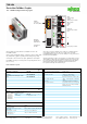
750-306
5 V
24 V
1) 2)
2) 10 nF /500 V
1) 1 MΩ
5 V
24 V
ELECTRONICS
I/O
modules
FIELDBUS
INTERFACE
FI ELDBUS
I NTERFA CE
ELECTRONICS
Technical Data
Number of I/O modules 64
Fieldbus
Max. input process image 512 bytes
Max. output process image 512 bytes
Configuration via PC or PLC
DeviceNet features Polled I/O message connection
Strobed I/O message connection
Change of state
Cyclic message connection
Group 2 only, slave
Power supply 24 V DC (-25 % ... +30 %)
Current consumption
via power supply terminal < 500 mA / 24 V
via DeviceNet interface < 120 mA / 11 V
Efficiency of the power supply 87 %
Internal current consumption (5 V) 350 mA
Total current for I/O modules (5 V) 1650 mA
Isolation 500 V system/supply
Voltage via power jumper contacts 24 V DC (-25 % ... +30 %)
Current via power jumper contacts (max.) 10 A DC
General Specifications
Operating temperature 0 °C ... +55 °C
Wire connection CAGE CLAMP
®
Cross sections 0.08 mm² ... 2.5 mm² / AWG 28 ... 14
Stripped lengths 8 ... 9 mm / 0.33 in
Dimensions (mm) W x H x L 51 x 65 x 100
Height from upper-edge of DIN 35 rail
Weight 202 g
Storage temperature -25 °C ... +85 °C
Relative air humidity (no condensation) 95 %
Vibration resistance acc. to IEC 60068-2-6
Shock resistance acc. to IEC 60068-2-27
Degree of protection IP20
EMC: 1 - immunity to interference acc. to EN 61000-6-2 (2005)
EMC: 1 - emission of interference acc. to EN 61000-6-4 (2007)
EMC: marine applications
- immunity to interference acc. to Germanischer Lloyd (2003)
EMC: marine applications
- emission of interference acc. to Germanischer Lloyd (2003)