
User Manual

Touch Panel Standard Line Properties 33
762-4xxx TP 600
Manual
Version 1.3.0
4.4 Connectors
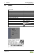
4.4.1 Connectors of Hardware PIO1
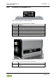
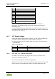
Figure 8: Connectors PIO1 on the Bottom (Example)
Table 6: Legend for Figure “Connectors PIO1 on the Bottom”
Connector
Function
X1 and X2
ETHERNET interfaces with LED indicators
X5
Supply voltage infeed
X6 and X7
USB 2.0 host interfaces
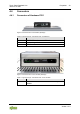
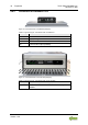
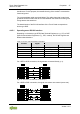
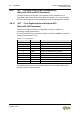
Figure 9: Connectors PIO1 on the Left Side (Example)
Table 7: Legend for Figure “Connectors PIO1 on the Left Side”
Connector
Function
microSD
Slot for microSD and microSDHC cards with cap,
sealable