
User Manual

Touch Panel Standard Line Properties 39
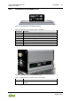
762-4xxx TP 600
Manual
Version 1.3.0
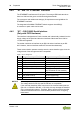
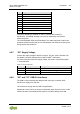
Table 1: X4 Pin Assignment
Pin
Assignment
1
-
2
CAN-L (CAN data low)
3
GND (reference potential 0 V or ground)
4
-
5
-
6
-
7
CAN-H (CAN data high)
8
-
9
-
Continuous shielding is essential in order to increase the immunity to
interference. The metallic housing of the plug is capacitively connected to
functional ground.
The connected data cable must be shielded. The cable clamp that is used must
guarantee sufficient strain relief and contact between the shield and housing over
a large area at the same time.
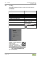
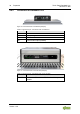
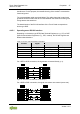
4.4.7 “X5” Supply Voltage
Connect the supply voltage to the X5 connector. For this, use the included 734-
103 female connector featuring three CAGE CLAMP
®
connections.
For more information about the supply voltage, see section “Device Description”
> “Technical Data”.
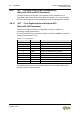
Table 13: X5 Pin Assignment
Pin
Description
Assignment
1
24VDC
Supply voltage: +24 VDC
2
GND
Reference potential 0V (ground)
3
FE
Functional earth
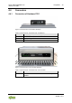
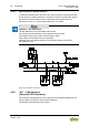
4.4.8 “X6” and “X7” USB-2.0 Interfaces
The USB 2.0 host interfaces are designed with 4-pin type A sockets. Each
interface can supply max. 500 mA.
The connectors comply with the USB 2.0 specification.
Keyboards or mice can be connected as alternative input devices or up to 2 USB
memory devices. These USB devices must be connected before power ON.