
User manual


EPSITRON® Table of Contents 3
787-1662 Electronic Circuit Breaker
Manual
Version 1.0.0
Pos: 5 /D ok ument ati on al lg em ein/V erz eic hni sse /Inh alts ver zei chni s - Ü bersc hrift oG und Ver zeich nis @ 3\mod_1219151230875_21.docx @ 21063 @ @ 1
Table of Contents
1 Notes about this Documentation ................................................................. 5
1.1 Validity of this Documentation ................................................................. 5
1.2 Copyright ................................................................................................... 5
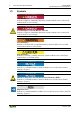
1.3 Symbols ..................................................................................................... 6
1.4 Number Notation ....................................................................................... 8
1.5 Font Conventions ...................................................................................... 8
2 Important Notes ........................................................................................... 9
2.1 Legal Bases ............................................................................................... 9
2.1.1 Subject to Changes ............................................................................... 9
2.1.2 Personnel Qualifications ....................................................................... 9
2.1.3 Use of the 787 Series in Compliance with Underlying Provisions ...... 9
2.1.4 Technical Condition of Specified Devices ......................................... 10
2.2 Safety Advice (Precautions) .................................................................... 11
3 Device Description ..................................................................................... 13
3.1 View ........................................................................................................ 14
3.2 Connectors ............................................................................................... 15
3.2.1 Power supply ...................................................................................... 15
3.2.2 Fuse-Protected Outputs ...................................................................... 16
3.2.3 Control and Signaling Contacts .......................................................... 16
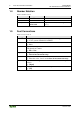
3.3 Display Elements .................................................................................... 17
3.4 Operating Elements ................................................................................. 18
3.4.1 Buttons ................................................................................................ 18
3.4.2 Rotary Switch ..................................................................................... 19
3.5 Technical Data ........................................................................................ 20
3.5.1 Device Data ........................................................................................ 20
3.5.2 Technical Data for "Input" ................................................................. 21
3.5.3 Technical Data for "Output" ............................................................... 22
3.5.4 Technical Data for "Ambient conditions" .......................................... 23
3.5.5 Technical Data for "Signaling" .......................................................... 23
3.6 Approvals ................................................................................................ 24
3.7 Standards and Guidelines ........................................................................ 25
4 Mounting ..................................................................................................... 26
4.1 Mounting ................................................................................................. 26
4.2 Mounting the Device on the DIN 35 Rail ............................................... 26
4.3 Removing the Device from the DIN 35 Rail .......................................... 27
5 Connect Devices ......................................................................................... 28
5.1 Connection Example ............................................................................... 28
6 Function Description ................................................................................. 29
6.1 Undervoltage and Overvoltage Detection ............................................... 29
6.2 Trip Curves .............................................................................................. 29
6.2.1 Trip Curve for the 10 A Circuit Breaker 787-1662 ............................ 29
6.2.2 Trip Curve for the 6 A Circuit Breaker 787-1662/0106-0000 ........... 30
6.2.3 Trip Curve for the 6 A Circuit Breaker with Active Current Limitation
787-1662/0006-1000 .......................................................................... 30