
Datasheet

1
1
51
8
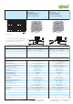
Relay with 1 changeover contact (1u)
(gold contacts)
for normal switching power
Nominal input voltage
V
N
24 V, 110 V, 220 V DC
Relay with 1 changeover contact (1u)
(gold contacts)
for normal switching power
Nominal input voltage
V
N
24 V, 115 V, 230 V AC/DC
DC load limit curve
* In order to prevent the gold layer from being damaged,
these values shall not be exceeded. Higher switching
power leads to evaporation of the gold layer.
In case of damaged gold layer, the values in parens apply.
Description
V
N
I
N
Item No.
Pack.
Unit
V
N
I
N
Item No.
Pack.
Unit
JUMPFLEX
®
relay socket with miniature switching
relay, for DIN 35 rail
24 V DC 10 mA 857-314 124 V AC/DC8.5 mA857-364 1
110 V DC 3.5 mA 857-317 1115 V AC/DC4 mA857-367 1
220 V DC 3.2 mA 857-318 1230 V AC/DC3.5 mA857-368 1
Technical Data
Accessories see pages 68 ... 71 Accessories see pages 68 ... 71
Contact material AgNi + 5 μ Au AgNi + 5 μ Au
Input voltage range V
N
-15 % ... +20 % V
N
-15 % ... +20 % (857-364/857-367)
V
N
-15 % ... +10 % (857-368)
Max. switching voltage 30 V* DC / (250 V AC/DC) (250 V AC/DC)*
Max. continuous current (terminal blocks in a row) 50 mA* / (6 A ) 30 V* DC / 50 mA* / (6 A )
Max. Switching power (resistive) (1250 VA AC; DC see load limit curve) (1250 VA AC; DC see load limit curve)
Recommended minimum load ≥ 1 V / 1 mA / 1 mW ≥ 1 V / 1 mA / 1 mW
Max. switching rate with / without load 6 min
-1
/ 20 s
-1
6 min
-1
/ 20 s
-1
Operating power < 300 mW / < 700 mW < 300 mVA / < 800 mVA
Pull-in/drop-out/bounce time typ. 5 ms / 6 ms / 5 ms 5 ms / 6 ms / 5 ms
Nominal operating mode continuous duty continuous duty
Dielectric strength contact-coil 4 kV
eff
4 kV
eff
Surge capacity open contact 1 kV
eff
1 kV
eff
Nominal voltage acc. to VDE 0110 Part 1/4.97,
IEC 60664-1 250 V / 4 kV / 3 250 V / 4 kV / 3
Mechanical life 5 x 10
6
switching operations 5 x 10
6
switching operations
Mechanical life at max. load (resistance) 5 x 10
4
switching operations 5 x 10
4
switching operations
Ambient operating temperature (V
N
) -25 °C ... +60 °C -25 °C ... +60 °C
Storage temperature -40 °C ... +70 °C -40 °C ... +70 °C
Dimensions (mm) W x H x L 6 x 81 x 94 6 x 81 x 94
Height from upper-edge of DIN 35 rail Height from upper-edge of DIN 35 rail
Wire connection CAGE CLAMP
®
SCAGE CLAMP
®
S
Cross sections 0.34 mm² ... 2.5 mm² / AWG 22 ... 14 0.34 mm² ... 2.5 mm² / AWG 22 ... 14
Stripped lengths 9 ... 10 mm / 0.37 in 9 ... 10 mm / 0.37 in
Approvals VDE 0110 / EN 60664; VDE 0435 / EN 61810-1; r
(857-314: g)
VDE 0110 / EN 60664; VDE 0435 / EN 61810-1; r
(857-368: g)
<______ 81 mm/3.18 in ______>
8
57
-
3
14
<_________ 94 mm/3.68 in _________>
____________
85
7
-
36
4
<_________ 94 mm/3.68 in _________>
____________
<______ 81 mm/3.18 in ______>
A2
A1
WAGO Kontakttechnik GmbH & Co. KG
Subject to design changes 01.07.2013
Postfach 2880 - D-32385 Minden
Hansastr. 27 - D-32423 Minden
Tel.: +49(0)571/887-0 E-Mail: info@wago.com
Fax: +49(0)571/887-169 www.wago.com