
Datasheet

3
223
3
▯ = ON
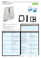
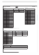
857--402DIP Switch Adjustability
DIP Switch S2
Output Signal Ranges Reserve Clipping Rocker Switch Lock
1 2 3 4 5 6 7 8
Default setting*
inactive
(analog response)
switched off
● 0 … 10 V ●
active
(limiting response)
● switched on
● ● ± 10 V
● ● 2 … 10 V
● 0 … 5 V
● ● ± 5 V
● ● 1 … 5 V
● ● 0 … 20 mA
● ● ● ± 20 mA
● ● ● 4 … 20 mA
● 0 … 10 mA
● ● ± 10 mA
● ● 2 … 10 mA
DIP Switch S1
Input Signal Ranges Zero/Span Adjustment
Max. Operating
Frequency
1 2 3 4 5 6 7 8
Default setting* Inactive < 100 Hz
● 0 … 60 mV ● Active ● ≥ 5 kHz
● ● ± 60 mV
● 0 … 100 mV
● ● ± 100 mV
● ● 0 … 150 mV
● ● ● ± 150 mV
● 0 … 300 mV
● ● ± 300 mV
● ● 0 … 500 mV
● ● ● ± 500 mV
● ● 0 … 1 V
● ● ● ± 1 V
● ● ● 0 … 5 V
● ● ● ● ± 5 V
● 0 … 10 V
● ● ± 10 V
● ● 0 ... 50 V
● ● ● ± 50 V
● ● 0 … 100 V
● ● ● ± 100 V
● ● ● 0 … 200 V
● ● ● ● ± 200 V
DIP Switch S1
Input Signal Ranges
123456
● ● 0 … 0.3 mA
● ● ● ± 0.3 mA
● ● ● 0 … 1 mA
● ● ● ● ± 1 mA
● ● ● 0 … 5 mA
● ● ● ● ± 5mA
● ● ● ● 0 … 10 mA
● ● ● ● ● ± 10 mA
● 0 … 20 mA
● ● ± 20 mA
● ● 0 … 50 mA
● ● ● ± 50 mA
● ● 0 … 100 mA
● ● ● ± 100 mA
● ● 1 … 5 V
● ● ● 2 … 10 V
● ● ● 2 … 10 mA
● ● ● ● 4 … 20 mA
*Default setting
Input ± 10 V
Output ± 10 V
Max. operating frequency > 5 kHz
* The input and output range DIP switches must be readjusted when changing the default setting.
More information on measurement range setting is available in 857-402 instruction leafl et.