
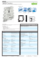
Datasheet

3
261
3
▯ = ON
857-531
DO
%
DO‘
t
100
!
!
75
0
0
0
configured
to 75 %
Measuring
input/
Measured
value
default
! Hysteresis
SP1
S11–
SP1
1
SP1 SP2
SP1 SP2
SP1SP2
SP1SP2
2
3
6
4
5
–
–1
2
2
2
2
–––
S1
S1 + S2
S1 + S2
S1 + S2
S1 + S2
Configuration
Number of
Switching
Thresholds
Leave param. mode without
storing a value
Switching
Behavior
Values for
Switching T
hresholds
Switching
Threshold 2,
Relay
Press
for
1 sec.
Yellow
LED
flashes
Switching
Threshold 1,
Relay
SP1
Param. mode
Leave
param. mode
SP1 SP2
Param. mode
Leave
param. mode
SP1
Param. mode
Leave
param. mode
SP1
SP2
Param. mode
Leave
param. mode
SP1 SP2
Param. mode
Leave
param. mode
SP1 SP2
Param. mode
Leave
param. mode
Param. mode
Leave
param. mode
Red LED
flashes
briefly
No
flashing
LED
„On“
„Off“
„On“
„Off“
„On“
„Off“ „On“
„Off“
„Off“
„On“
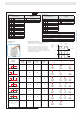
DIP Switch Adjustability
DIP Switch S1
Confi gurable
rise/fall delay time in sec.
Digital output DO
Signaling
678 910
0 DO not active
●1● GND → U
N
(switching)
●2●● U
N
→ GND
(switching)
●● 3
●4
●● 5
●● 8
●●● 10
DIP Switch S1
Input signal limits
± 0.25 V; ± 0.5 mA
Hysteresis
1234 5
±10 V 5 mV; 10 μA
● 0 … 10 V ● 10 mV, 20 μA
● 2 … 10 V
● ● 0 … 5 V
● 1 … 5 V
● ● ± 5 V
● ● 0 … 15 V
● ● ● 0 … 30 V
● ± 20 mA
● ● 0 … 20 mA
● ● 4 … 20 mA
● ● ● 0 … 10 mA
● ● 2 … 10 mA
● ● ● ± 10 mA
Default Settings
All DIP switches are in „OFF“ position for delivery.
Input
Input range ± 10 V
Hysteresis 5 mV
Output
Confi gurable rise/fall delay time 0 s
Digital output DO not active
Push/Slide Switch
Operation
Switching Behavior, Digital Output (DO)
The digital output (DO) signals error messages and can be
confi gured as follows: 24 V → 0 V/0 V → 24 V.
In order to increase the switching current of the DO, the
latter may be expanded by a relay. Thanks to the contour
uniformity of Series 857, for example, a 857-304 Relay
can be snapped in next to it. This output can be quickly and
easily expanded to a switching current of 6A by simply using
an adjacent jumper (859-402).
Digital Output DO/Signaling