
Technical data

24 • The WAGO-I/O-SYSTEM 750
Mechanical Setup
WAGO-I/O-SYSTEM 750
INTERBUS
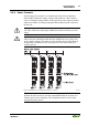
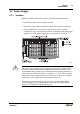
2.6.5 Plugging and Removal of the Components
Warning
Before work is done on the components, the voltage supply must be turned off.
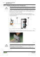
In order to safeguard the coupler/controller from jamming, it should be fixed
onto the carrier rail with the locking disc To do so, push on the upper groove
of the locking disc using a screwdriver.
To pull out the field bus coupler/controller, release the locking disc by
pressing on the bottom groove with a screwdriver and then pulling the orange
colored unlocking lug .
Fig. 2-5: Coupler/Controller and unlocking lug g01xx12e
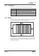
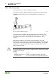
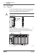
It is also possible to release an individual I/O module from the unit by pulling
an unlocking lug.
Fig. 2-6: removing bus terminal p0xxx01x
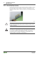
Danger
Ensure that an interruption of the PE will not result in a condition which
could endanger a person or equipment!
For planning the ring feeding of the ground wire, please see chapter 2.6.3.