
Technical data

Assembly Sequence • 25
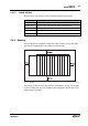
WAGO DIN Rail
WAGO-I/O-SYSTEM 750
INTERBUS
2.6.6 Assembly Sequence
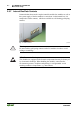
All system components can be snapped directly on a carrier rail in accordance
with the European standard EN 50022 (DIN 35).
The reliable positioning and connection is made using a tongue and groove
system. Due to the automatic locking, the individual components are securely
seated on the rail after installing.
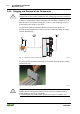
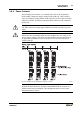
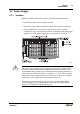
Starting with the coupler/controller, the bus modules are assembled adjacent to
each other according to the project planning. Errors in the planning of the node
in terms of the potential groups (connection via the power contacts) are
recognized, as the bus modules with power contacts (male contacts) cannot be
linked to bus modules with fewer power contacts.
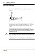
Attention
Always link the bus modules with the coupler/controller, and always plug
from above.
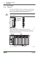
Warning
Never plug bus modules from the direction of the end terminal. A ground
wire power contact, which is inserted into a terminal without contacts, e.g. a
4-channel digital input module, has a decreased air and creepage distance to
the neighboring contact in the example DI4.
Always terminate the field bus node with an end module (750-600).