
Technical data


50 • Feldbus Coupler 750-344 / -345
Hardware
WAGO-I/O-SYSTEM 750
INTERBUS
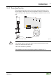
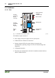
3.1.2.3 Fieldbus Connection
The WAGO-I/O SYSTEM 750 for INTERBUS is equipped with two 9-pole
D-SUB connectors for fieldbus connection. INTERBUS makes a distinction
between the "incoming" and "outgoing" interface.
5
9
8
7
6
4
3
2
1
GND1
DI1
DI1
DO1
DO1
VCC1
n.c.
GND1
VCC1
Input interface: 9 pole D-Sub (male)
Fig. 3-3: "Connector" terminal assignment g012231e
The incoming interface provides electrical isolation between the fieldbus and
the bus coupler.
1
6
7
8
9
2
3
4
5
+5V
RBST
DI2
DO2
DO2
DI2
GND
n.c.
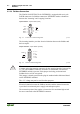
Output interface: 9 pole D-Sub (female)
Fig. 3-4: "Socket" terminal assignment g012229e
Note
A jumper in the plug (mating connector) for the outgoing interface between Pin
5 (+5 V) and 9 (RBST) causes the electronics to assume that a downcircuit
INTERBUS module is present. If this jumper is missing, no downcircuit
fieldbus devices will be recognized.
This jumper is already present in the plug for standard cables fabricated based
on the INTERBUS standard.
The +5 V voltage may not be used for other purposes.
Electrical isolation between the fieldbus interface and the internal electronics
is provided via an internal power supply unit and optocouplers.
The connection point of the coupler is lowered to fit in an 80mm high switch
box once connected to the INTERBUS connector.