
Technical data


54 • Feldbus Coupler 750-344 / -345
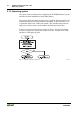
Process Image
WAGO-I/O-SYSTEM 750
INTERBUS
Based on this break-down, the first addresses assigned in the configuration are
reserved for analog inputs and outputs. Counting is from left to right,
beginning with the first analog channel next to the bus coupler.
3.1.4.3 Bus Modules Process Images on the Interbus
The status bytes (S), control bytes (C) and data bytes (D0...Dn) for for byte-
and word-oriented modules are mapped in the Motorola format on the
Interbus.
NOTE:
For the significance of input and output bits/bytes of the individual I/O
modules, please refer to the corresponding description of the I/O modules.
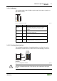
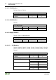
3.1.4.3.1 2 DI Modules
750-400, 750-401, 750-405, 750-406, 750- 410, 750-411,750-412
Process Image in [Bit]
Input Output
INTERBUS 2 0
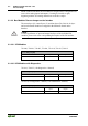
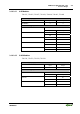
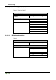
3.1.4.3.2 2 DI Modules with Diagnostics
750-419, 750-425 (1 bit diagnostics / channel)
Process Image in [Bit]
Input Output
INTERBUS 4 0
750-418 (1 bit diagnostics / channel, 1 bit confirmation / channel)
Process Image in [Bit]
Input Output
INTERBUS 4 4