
Technical data


62 • Feldbus Coupler 750-344 / -345
Configuration
WAGO-I/O-SYSTEM 750
INTERBUS
3.1.5 Configuration
3.1.5.1 INTERBUS Files
Further information
INTERBUS files for configuring I/O modules are available under item
number 750-913 on disk, or at the WAGO Internet site.
http://www.wago.com
3.1.5.2 ID Code
During the ID cycle, which is performed for initialization of the INTERBUS
system, the connected subscribers (slaves) "declare" themselves by their
function and their byte length. The INTERBUS fieldbus coupler determines
the length of the system after power on during the initialization phase of the
I/O modules and generates a corresponding ID code. Each slave has a 2-byte
ID register implemented for this.
Different types of slaves and data widths are used for coding on the
INTERBUS. The enables the master to establish which devices belong to
which device categories, i.e., to recognize frequency converters or I/O units
such as the WAGO-I/O-SYSTEM. Device types or manufacturers are not
recognized. An explanation of how the ID code is set up and the meaning of
the individual bits of this ID code is given below.
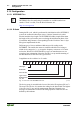
Length data can be coded as 0 to 32 words:
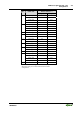
15 14 13 12 11 10 9 8 7 6 5 4 3 2 1 0
Data direction
I, O, I/O
Data width
Type of user
Messages
Class of user
Fig. 3-8: Structure of the INTERBUS ID code g012233e
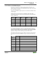
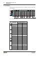
The device group is encoded in the lowest 8 bits in the ID registers (ID 0 to7).
The next 5 bits (ID 8 to 12) contains the coding for the data width. The highest
3 bits (ID 13 to 15) are used for management functions. Dynamic error
messages are transmitted via these bits during operation. These bits are not
defined by the hardware.