
Technical data


INTERBUS • 79
WAGO-I/O-SYSTEM 750
INTERBUS
The subscribers are assigned their address automatically based on their
physical position in the bus system. Control signals (CLOCK, RESET,
SELECT, CONTROL) allow each single subscriber to be monitored.
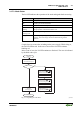
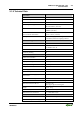
Each subscriber has its own ID register that contains information about the
type of module, number of I/O addresses and status and error status data.
The INTERBUS uses two operating modes:
1. ID Cycle
In the ID cycle the interface module exports the ID registers from all
devices connected to the bus system and sets up the process map using this
information. This cycle is used for initialization and is performed on
request.
2. Data Cycle
In the data cycle the input data from all of the devices is transmitted from
the registers to the master and output data transferred from the master to the
devices.
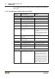
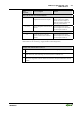
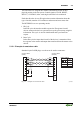
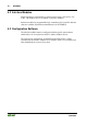
5.1.2.1 Example of remote bus cable
Standard 9-pole D-SUB plugs or sockets can be used as connectors.
11
22
33
44
55
66
77
88
99
DI DI
DO DO
GND GND
DI DI
DO DO
DO - DO
DI-DI
GND
DO DO-
DI DI-
9 pole D-SUB
(female)
Color coding
Yellow
Green
Grey
Pink
Brown
9 pole D-SUB
(male)
Jumper
Cable
grip/
Hous-
ing
Cable
grip/
Hous-
ing
Fig. 5-2: Example of a remote bus cable g012235d