Modular I/O-System ETHERNET TCP/IP 750-841 Manual Technical description, installation and configuration Version 1.0.
ii • General Copyright 2003 by WAGO Kontakttechnik GmbH All rights reserved.. WAGO Kontakttechnik GmbH Hansastraße 27 D-32423 Minden Phone: +49 (0) 571/8 87 – 0 Fax: +49 (0) 571/8 87 – 1 69 E-Mail: info@wago.com Web: http://www.wago.com Technical Support Phone: +49 (0) 571/8 87 – 5 55 Fax: +49 (0) 571/8 87 – 85 55 E-Mail: support@wago.com Every conceivable measure has been taken to ensure the correctness and completeness of this documentation.
Table of Contents • iii TABLE OF CONTENTS 1 Important Comments ................................................................................ 1 1.1 Legal Principles...................................................................................... 1 1.2 Symbols.................................................................................................. 2 1.3 Font Conventions ................................................................................... 3 1.4 Number Notation ................
iv • Table of Contents 7 Ethernet/IP (Ethernet/Industrial Protocol) ......................................... 172 7.1 General ............................................................................................... 172 7.2 Characteristics of the Ethernet/IP Protocol Software......................... 173 7.3 Object model...................................................................................... 174 8 Application examples......................................................................
Important Comments Legal Principles • 1 1 Important Comments To ensure fast installation and start-up of the units described in this manual, we strongly recommend that the following information and explanations are carefully read and abided by. 1.1 Legal Principles 1.1.1 Copyright This manual is copyrighted, together with all figures and illustrations contained therein. Any use of this manual which infringes the copyright provisions stipulated herein, is not permitted.
2 • Important Comments Symbols 1.2 Symbols Danger Always abide by this information to protect persons from injury. Warning Always abide by this information to prevent damage to the device. Attention Marginal conditions must always be observed to ensure smooth operation. ESD (Electrostatic Discharge) Warning of damage to the components by electrostatic discharge. Observe the precautionary measure for handling components at risk.
Important Comments Font Conventions 1.3 Font Conventions Italic Names of path and files are marked italic i.e.: C:\programs\WAGO-IO-CHECK Italic Menu items are marked as bold italic i.e.: Save \ A backslash between two names marks a sequence of menu items i.e.: File\New END Press buttons are marked as bold with small capitals i.e.: ENTER <> Keys are marked bold within angle brackets i.e.: Courier Program code is printed with the font Courier. i.e.: END_VAR 1.
4 • Important Comments Safety Notes 1.5 Safety Notes Attention Switch off the system prior to working on bus modules! In the event of deformed contacts, the module in question is to be replaced, as its functionality can no longer be ensured on a long-term basis. The components are not resistant against materials having seeping and insulating properties. Belonging to this group of materials is: e.g. aerosols, silicones, triglycerides (found in some hand creams).
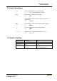
Important Comments Scope • 5 1.6 Scope This manual describes the field bus independent WAGO-I/O-SYSTEM 750 with the programmable fieldbus controller for ETHERNET 10/100 MBit/s. Item.-No. Description 750-841 Prog. Fieldbus Controller EtherNet 10/100 MBit/s 1.7 Important Comments for Starting up Attention For the start-up of the controller 750-841 important notes are to be considered, because it strongly differentiates in some points of starting up the controller 750-842. Read for this the chapter: 3.1.
6 • The WAGO-I/O-SYSTEM 750 System Description 2 The WAGO-I/O-SYSTEM 750 2.1 System Description The WAGO-I/O-SYSTEM 750 is a modular, fieldbus independent I/O system. It is comprised of a fieldbus coupler/controller (1) and up to 64 connected fieldbus modules (2) for any type of signal. Together, these make up the fieldbus node. The end module (3) completes the node. Fig.
The WAGO-I/O-SYSTEM 750 Technical Data • 7 2.2 Technical Data Mechanic Material Polycarbonate, Polyamide 6.
8 • The WAGO-I/O-SYSTEM 750 Technical Data Mechanical strength Vibration resistance acc. to IEC 60068-2-6 Comment to the vibration restistance: a) Type of oscillation: sweep with a rate of change of 1 octave per minute 10 Hz ≤ f < 57 Hz, const. Amplitude 0,075 mm 57 Hz ≤ f < 150 Hz, const. Acceleration 1 g b) Period of oscillation: 10 sweep per axis in each of the 3 vertical axes Shock resistance acc.
The WAGO-I/O-SYSTEM 750 Technical Data Range of application Required specification emission of interference Required specification immunity to interference Industrial areas EN 50081-2 : 1993 EN 50082-2 : 1996 Residential areas EN 50081-1 : 1993*) EN 50082-1 : 1992 • 9 *) The system meets the requirements on emission of interference in residential areas with the fieldbus coupler/controller for: ETHERNET 750-342/-841/-842 LonWorks 750-319/-819 CANopen 750-337/-837 DeviceNet 750-306/-806 MODBU
10 • The WAGO-I/O-SYSTEM 750 Technical Data Dimensions Fig.
The WAGO-I/O-SYSTEM 750 Manufacturing Number • 11 2.3 Manufacturing Number The production number is part of the lateral marking on the component. Fig. 2-3: Manufacturing Number g01xx09e The manufacturing number consists of the production week and year, the software version (if available), the hardware version of the component, the firmware loader (if available) and further internal information for WAGO Kontakttechnik GmbH.
12 • The WAGO-I/O-SYSTEM 750 Storage, Assembly and Transport 2.4 Storage, Assembly and Transport Wherever possible, the components are to be stored in their original packaging. Likewise, the original packaging provides optimal protection during transport. When assembling or repacking the components, the contacts must not be soiled or damaged. The components must be stored and transported in appropriate containers/packaging. Thereby, the ESD information is to be regarded.
The WAGO-I/O-SYSTEM 750 Mechanical Setup • 13 2.5.3 Assembly onto Carrier Rail 2.5.3.1 Carrier rail properties All system components can be snapped directly onto a carrier rail in accordance with the European standard EN 50022 (DIN 35). Warning WAGO supplies standardized carrier rails that are optimal for use with the I/O system. If other carrier rails are used, then a technical inspection and approval of the rail by WAGO Kontakttechnik GmbH should take place.
14 • The WAGO-I/O-SYSTEM 750 Mechanical Setup 2.5.3.2 WAGO DIN Rail WAGO carrier rails meet the electrical and mechanical requirements. Item Number Description 210-113 /-112 35 x 7.5; 1 mm; steel yellow chromated; slotted/unslotted 210-114 /-197 35 x 15; 1.5 mm; steel yellow chromated; slotted/unslotted 210-118 35 x 15; 2.3 mm; steel yellow chromated; unslotted 210-198 35 x 15; 2.3 mm; copper; unslotted 210-196 35 x 7.5; 1 mm; aluminum; unslotted 2.5.
The WAGO-I/O-SYSTEM 750 Mechanical Setup • 15 2.5.5 Plugging and Removal of the Components Warning Before work is done on the components, the voltage supply must be turned off. In order to safeguard the coupler/controller from jamming, it should be fixed onto the carrier rail with the locking disc To do so, push on the upper groove of the locking disc using a screwdriver.
16 • The WAGO-I/O-SYSTEM 750 Mechanical Setup 2.5.6 Assembly Sequence All system components can be snapped directly on a carrier rail in accordance with the European standard EN 50022 (DIN 35). The reliable positioning and connection is made using a tongue and groove system. Due to the automatic locking, the individual components are securely seated on the rail after installing. Starting with the coupler/controller, the bus modules are assembled adjacent to each other according to the project planning.
The WAGO-I/O-SYSTEM 750 Mechanical Setup • 17 2.5.7 Internal Bus / Data Contacts Communication between the coupler/controller and the bus modules as well as the system supply of the bus modules is carried out via the internal bus. It is comprised of 6 data contacts, which are available as self-cleaning gold spring contacts. Fig.
18 • The WAGO-I/O-SYSTEM 750 Mechanical Setup 2.5.8 Power Contacts Self-cleaning power contacts , are situated on the side of the components which further conduct the supply voltage for the field side. These contacts come as touchproof spring contacts on the right side of the coupler/controller and the bus module. As fitting counterparts the module has male contacts on the left side. Danger The power contacts are sharp-edged. Handle the module carefully to prevent injury.
The WAGO-I/O-SYSTEM 750 Mechanical Setup • 19 2.5.9 Wire connection All components have CAGE CLAMP® connections. The WAGO CAGE CLAMP® connection is appropriate for solid, stranded and fine–stranded conductors. Each clamping unit accommodates one conductor. Fig. 2-9: CAGE CLAMP® Connection g0xxx08x The operating tool is inserted into the opening above the connection. This opens the CAGE CLAMP®. Subsequently the conductor can be inserted into the opening.
20 • The WAGO-I/O-SYSTEM 750 Power Supply 2.6 Power Supply 2.6.1 Isolation Within the fieldbus node, there are three electrically isolated potentials. • Operational voltage for the fieldbus interface. • Electronics of the couplers / controllers and the bus modules (internal bus). • All bus modules have an electrical isolation between the electronics (internal bus, logic) and the field electronics. Some analog input modules have each channel electrically isolated, please see catalog. Fig.
The WAGO-I/O-SYSTEM 750 Power Supply • 21 2.6.2 System Supply 2.6.2.1 Connection The WAGO-I/O-SYSTEM 750 requires a 24 V direct current system supply (-15% or +20 %). The power supply is provided via the coupler / controller and, if necessary, in addition via the internal system supply modules (750-613). The voltage supply is reverse voltage protected. Fig. 2-11: System Supply g0xxx02e The direct current supplies all internal system components, e.g.
22 • The WAGO-I/O-SYSTEM 750 Power Supply 2.6.2.2 Alignment Recommendation A stable network supply cannot be taken for granted always and everywhere. Therefore, regulated power supply units should be used in order to guarantee the quality of the supply voltage. The supply capacity of the coupler/controller or the internal system supply module (750-613) can be taken from the technical data of the components.
The WAGO-I/O-SYSTEM 750 Power Supply • 23 The maximum input current of the 24 V system supply is 500 mA.
24 • The WAGO-I/O-SYSTEM 750 Power Supply 2.6.3 Field Supply 2.6.3.1 Connection Sensors and actuators can be directly connected to the relevant channel of the bus module in 1-/4 conductor connection technology. The bus module supplies power to the sensors and actuators. The input and output drivers of some bus modules require the field side supply voltage. The coupler/controller provides field side power (DC 24V). Power supply modules are available for other potentials, e.g. AC 230 V.
The WAGO-I/O-SYSTEM 750 Power Supply • 25 Attention Some bus modules have no or very few power contacts (depending on the I/O function). Due to this, the passing through of the relevant potential is disrupted. If a field supply is required for subsequent bus modules, then a power supply module must be used. Note the data sheets of the bus modules. In the case of a node setup with different potentials, e.g. the alteration from DC 24 V to AC 230V, a spacer module should be used.
26 • The WAGO-I/O-SYSTEM 750 Power Supply Warning In the case of power supply modules with fuse holders, only fuses with a maximum dissipation of 1.6 W (IEC 127) must be used. For UL approved systems only use UL approved fuses. In order to insert or change a fuse, or to switch off the voltage in succeeding bus modules, the fuse holder may be pulled out. In order to do this, use a screwdriver for example, to reach into one of the slits (one on both sides) and pull out the holder. Fig.
The WAGO-I/O-SYSTEM 750 Power Supply • 27 Alternatively, fusing can be done externally. The fuse modules of the WAGO series 281 and 282 are suitable for this purpose. Fig. 2-18: Fuse modules for automotive fuses, Series 282 pf66800x Fig. 2-19: Fuse modules with pivotable fuse carrier, Series 281 pe61100x Fig.
28 • The WAGO-I/O-SYSTEM 750 Power Supply 2.6.4 Supplementary power supply regulations The WAGO-I/O-SYSTEM 750 can also be used in shipbuilding or offshore and onshore areas of work (e.g. working platforms, loading plants). This is demonstrated by complying with the standards of influential classification companies such as Germanischer Lloyd and Lloyds Register. Filter modules for 24-volt supply are required for the certified operation of the system. Item No.
The WAGO-I/O-SYSTEM 750 Power Supply • 29 2.6.5 Supply example Note The system supply and the field supply should be separated in order to ensure bus operation in the event of a short-circuit on the actuator side.
30 • The WAGO-I/O-SYSTEM 750 Power Supply 2.6.6 Power Supply Unit The WAGO-I/O-SYSTEM 750 requires a 24 V direct current system supply with a maximum deviation of -15% or +20 %. Recommendation A stable network supply cannot be taken for granted always and everywhere. Therefore, regulated power supply units should be used in order to guarantee the quality of the supply voltage. A buffer (200 µF per 1 A current load) should be provided for brief voltage dips. The I/O system buffers for approx 1 ms.
The WAGO-I/O-SYSTEM 750 Grounding • 31 2.7 Grounding 2.7.1 Grounding the DIN Rail 2.7.1.1 Framework Assembly When setting up the framework, the carrier rail must be screwed together with the electrically conducting cabinet or housing frame. The framework or the housing must be grounded. The electronic connection is established via the screw. Thus, the carrier rail is grounded.
32 • The WAGO-I/O-SYSTEM 750 Grounding 2.7.2 Grounding Function The grounding function increases the resistance against disturbances from electro-magnetic interferences. Some components in the I/O system have a carrier rail contact that dissipates electro-magnetic disturbances to the carrier rail. Fig. 2-23: Carrier rail contact g0xxx10e Attention Care must be taken to ensure the direct electrical connection between the carrier rail contact and the carrier rail. The carrier rail must be grounded.
The WAGO-I/O-SYSTEM 750 Grounding • 33 2.7.3 Grounding Protection For the field side, the ground wire is connected to the lowest connection terminals of the power supply module. The ground connection is then connected to the next module via the Power Jumper Contact (PJC). If the bus module has the lower power jumper contact, then the ground wire connection of the field devices can be directly connected to the lower connection terminals of the bus module.
34 • The WAGO-I/O-SYSTEM 750 Shielding (Screening) 2.8 Shielding (Screening) 2.8.1 General The shielding of the data and signal conductors reduces electromagnetic interferences thereby increasing the signal quality. Measurement errors, data transmission errors and even disturbances caused by overvoltage can be avoided. Attention Constant shielding is absolutely required in order to ensure the technical specifications in terms of the measurement accuracy.
The WAGO-I/O-SYSTEM 750 Assembly Guidelines / Standards • 35 2.8.4 WAGO Shield (Screen) Connecting System The WAGO Shield Connecting system includes a shield clamping saddle, a collection of rails and a variety of mounting feet. Together these allow many dfferent possibilities. See catalog W3 volume 3 chapter 7. Fig. 2-25: WAGO Shield (Screen) Connecting System p0xxx08x, p0xxx09x, and p0xxx10x Fig. 2-26: Application of the WAGO Shield (Screen) Connecting System p0xxx11x 2.
36 • Fieldbus Controller Fieldbus Controller 750-841 3 Fieldbus Controller 3.1 Fieldbus Controller 750-841 This chapter includes: 3.1.1 3.1.2 3.1.2.1 3.1.2.2 3.1.2.3 3.1.2.4 3.1.2.5 3.1.2.6 3.1.2.7 3.1.3 3.1.3.1 3.1.3.2 3.1.4 3.1.4.1 3.1.4.2 3.1.4.3 3.1.5 3.1.5.1 3.1.5.2 3.1.5.3 3.1.5.4 3.1.5.5 3.1.5.6 3.1.6 3.1.6.1 3.1.6.2 3.1.6.3 3.1.6.4 3.1.6.5 3.1.6.6 3.1.7 3.1.7.1 3.1.7.2 3.1.7.3 3.1.8 3.1.8.1 3.1.8.2 3.1.8.3 3.1.8.4 3.1.8.5 Description................................................................
Fieldbus Controller Fieldbus Controller 750-841 3.1.8.6 3.1.9 3.1.9.1 3.1.9.2 3.1.10 WAGO-I/O-SYSTEM 750 ETHERNET TCP/IP • 37 Supply voltage status ............................................................. 100 Fault behavior ............................................................................... 100 Fieldbus failure ...................................................................... 100 Internal bus fault ....................................................................
38 • Fieldbus Controller 750-841 Description 3.1.1 Description The WAGO 750-841 Programmable Fieldbus Controller (PFC) combines the functionality of an ETHERNET fieldbus coupler with the functionality of a Programmable Logic Controller (PLC). When the PFC is used as a PLC, all or some of its I/O modules can be control locally with the use of WAGO-I/OPRO CAA. WAGO-I/O-PRO CAA is an IEC 61131-3 programming tool that is used to program and configure the 750-841 PFC.
Fieldbus Controller 750-841 Hardware • 39 addition, a file system is implemented that allows you to store custom HTML pages in the controller using FTP download. 3.1.2 Hardware 3.1.2.
40 • Fieldbus Controller 750-841 Hardware 3.1.2.2 Device Supply 5 2 6 24 V 24 V /0 V 10 nF DC DC 0V 24 V ELECTRONIC 3 7 0V 4 I/O MODULES 0V FiELDBUS INTERFACE 1 24 V ELECTRONIC FiELDBUS INTERFACE The PFC is powered via terminal blocks with CAGE CLAMP® connections. The Device Supply generates the necessary voltages to power the electronics of the controller and the internal electronics of the connected I/O modules. 10 nF 8 750-841 Fig.
Fieldbus Controller 750-841 Hardware • 41 3.1.2.3 Fieldbus Connection Connection to the fieldbus is by a RJ45 connector. The RJ45 socket on the fieldbus controller is wired per the 100BaseTX standard. The specification for the connecting cable is a twisted pair cable of Category 5. Cables of type SUTP (Screened-Unshielded Twisted Pair) and STP (Shielded Twisted Pair) with a maximum segment length of 100 meters may be used.
42 • Fieldbus Controller 750-841 Hardware LED LINK MS NS TxD/RxD IO Color green red/green red/green green red /green / orange red /green / orange Meaning Link to a physical network exists The ‚MS‘-LED indicates the state of the node (Module State) The ‚NS‘-LED indicates the state of the network (Network State) Data exchange taking place The 'I/O'-LED indicates the operation of the node and signals faults encountered The 'USR' LED can be controlled by a user program in a controller A green Status of t
Fieldbus Controller 750-841 Hardware • 43 3.1.2.6 Operating Mode Switch The operating mode switch is located behind a cover flap. RUN STOP RESET (pushing down) UPDATE FIRMWARE Mode switch Fig. 3-4: Operating Mode Switch g01xx10e The switch is a push/slide switch with 3 settings and a hold-to-run function. The slide switch is designed for a maximum number of switching cycles as defined in EN61131T2.
44 • Fieldbus Controller 750-841 Hardware Attention If outputs are set when switching from RUN to STOP mode, they remain set! Switching off the outputs on the software side i.e. by the initiators are ineffective because the program is no longer processed. Note With "GET_STOP_VALUE" (library "System.lib") WAGO-I/O-PRO CAA provides a function which recognizes the last cycle prior to a program being stopped.
Fieldbus Controller 750-841 Operating System • 45 3.1.3 Operating System 3.1.3.1 Start-up The controller starts-up after switching on the supply voltage or after a hardware reset. Note The Operating Mode slide switch must not be in the bottom position during start-up! The PLC program in the flash memory is transferred to RAM. This is followed by the initialization of the system. The controller determines the I/O modules and the present configuration.
46 • Fieldbus Controller 750-841 Operating System Switching on the supply voltage “I/O” LED is blinking orange Is a PLC program in the Flash memory ? No Yes PLC program transfer from the flash memory to RAM Determination of the I/O modules and the configuration Variables are set to 0 or FALSE or to their initial value, flags remain in the same status. Initialization of the system “I/O” LED is blinking red Test o.k.
Fieldbus Controller 750-841 Process Image • 47 3.1.4 Process Image The powered-up controller recognizes all I/O modules connected in the node that are waiting to transmit or receive data (data width/bit width > 0). The maximal length of a node is limited to 64 I/O modules. Note Use of the WAGO 750-628 Bus Extension Coupler Module and the 750-627 Extension End Module enables support of up to 255 I/O modules on the 750-841 controller.
48 • Fieldbus Controller 750-841 Process Image The MODBUS PFC variables are mapped after the process image of the I/O modules. This memory area contains 256 words (word 256 to 511). If the quantity of I/O data is greater than 256 words, the additional data is appended after the MODBUS PFC variables in word 512 to 1275. Like the first physical I/O process image area, there is a separate memory area for input and output data, but both are referenced with an index of 512 to 1275 for word operations.
Fieldbus Controller 750-841 Process Image • 49 3.1.4.1 Example of a Process Input Image The following figure is an example of a process input image. The configuration includes 16 digital and 8 analog inputs. Therefore, the process image has a total data length of 9 words (8 words for the analog data and 1 word for the digital inputs).
50 • Fieldbus Controller 750-841 Process Image 3.1.4.2 Example of a Process Output Image The following figure is an example of a process output image. The configuration includes 2 digital and 4 analog outputs. Therefore, the process image has a total data length of 5 (4 words for the analog data and 1 word for the digital outputs). When using MODBUS protocol, output data can be read back with an offset of 200hex (0x0200) added to the MODBUS address.
Fieldbus Controller 750-841 Process Image • 51 3.1.4.3 Fieldbus specific Process Data Architecture for MODBUS/TCP With some I/O modules, the structure of the process data is fieldbus specific. In the case of an Ethernet TCP/IP controller, the process image uses a word structure (with word alignment). The internal mapping method for data greater than one byte conforms to the Intel format.
52 • Fieldbus Controller 750-841 Process Image 2 Channel Digital Input Modules with Diagnostics 750-419, -424, -425 Bit 7 Bit 6 Bit 5 Bit 4 Bit 3 Diagnostic bit S 2 Channel 2 Bit 2 Diagnostic bit S 1 Channel 1 Bit 1 Data bit DI 2 Channel 2 Bit 0 Data bit DI 1 Channel 1 2 Channel Digital Input Module with Diagnostics and Output Process Data 750-418 The 750-418 digital input module supplies a diagnostic and acknowledge bit for each input channel.
Fieldbus Controller 750-841 Process Image • 53 3.1.4.3.2 Digital Output Modules Digital output modules use one bit of data per channel to control the output of the corresponding channel. These bits are mapped into the Output Process Image. When analog output modules are also present in the node, the digital image data is always appended after the analog data in the Output Process Image, grouped into bytes.
54 • Fieldbus Controller 750-841 Process Image Output Process Image Bit 7 Bit 6 Bit 5 Bit 4 Bit 3 Bit 2 Bit 1 controls DO 2 Channel 2 Bit 0 controls DO 1 Channel 1 750-506 The 750-506 digital output module has 2-bits of diagnostic information for each output channel. The 2-bit diagnostic information can then be decoded to determine the exact fault condition of the module (i.e., overload, a short circuit, or a broken wire).
Fieldbus Controller 750-841 Process Image • 55 3.1.4.3.3 Analog Input Modules The hardware of an analog input module has 16 bits of measured analog data per channel and 8 bits of status. However, the Ethernet controller does not have access to the 8 status bits. Therefore, the Ethernet controller can only access the 16 bits of analog data per channel, which are grouped as words and mapped in Intel format in the Input Process Image.
56 • Fieldbus Controller 750-841 Process Image 3.1.4.3.4 Analog Output Modules The hardware of an analog output module has 16 bits of analog output data per channel and 8 status bits. However, the Ethernet controller does not have access to the 8 status bits. Therefore, the Ethernet controller can only supply the 16 bits of analog data per channel, which is grouped as words and mapped in Intel format in the Output Process Image.
Fieldbus Controller 750-841 Process Image • 57 Counter Modules: 750-404, /000-000, /000-001, /000-002, /000-003, /000-004 The above 750-404 Counter Modules have a total of 5 bytes of user data in both the Input and Output Process Image (4 bytes of counter data and 1 byte of control/status). The counter value is supplied as 32 bits. The following tables illustrate the Input and Output Process Image, which has 3 words mapped into each image. Word alignment is applied.
58 • Fieldbus Controller 750-841 Process Image 750-638 The 750-638 counter module has a total of 6 bytes of user data in both the Input and Output Process Image (4 bytes of counter data and 2 bytes of control/status). The two counter values are supplied as 16 bits. Each counter has its own control/status byte. The following tables illustrate the Input and Output Process Image, which has 4 words mapped into each image. Word alignment is applied.
Fieldbus Controller 750-841 Process Image • 59 Input and Output Process Image Offset Byte Destination Remark High Byte Low Byte 0 - C0/S0 Control/Status byte of Channel 1 1 D1 D0 Data Value of Channel 1 2 - C1/S1 Control/Status byte of Channel 2 3 D3 D2 Data Value of Channel 2 Serial Interface Modules with alternative Data Format 750-650, /000-002, -004, -006, -007, -008, -009, -010, -011, -012, -013, -017, -020, -021, -023 750-651, /000-002, -003, -004, -006 750-653, /000-001, -002,
60 • Fieldbus Controller 750-841 Process Image 750-654, -630 The 750-654 Data Exchange module and the 750-630 Incremental Encoder Interface module have a total of 4 bytes of user data in both the Input and Output Process Image. The following table illustrates the Input and Output Process Image, which has 2 words mapped into each image. Word alignment is applied.
Fieldbus Controller 750-841 Process Image • 61 750-631/000-003, -005, -007 The above 750-631 Incremental Encoder Interface modules have 4 bytes of input data. The following table illustrates the Input Process Image, which has 2 words mapped into the image. Word alignment is applied.
62 • Fieldbus Controller 750-841 Process Image 750-637 The 750-637 Incremental Encoder Interface Module has a total of 6 bytes of user data in both the Input and Output Process Image (4 bytes of encoder data and 2 bytes of control/status). The following table illustrates the Input and Output Process Image, which has 4 words mapped into each image. Word alignment is applied.
Fieldbus Controller 750-841 Data Exchange • 63 3.1.5 Data Exchange The ETHERNET TCP/IP fieldbus controller can be configured for either MODBUS/TCP or the Ethernet IP protocol. MODBUS/TCP works according to the master/ model. The master (e.g., a PC or a PLC) will query a slave device and the slave will return a response to the master depending on the kind of query. Queries are addressed to a specific node through the use of the IP address.
64 • Fieldbus Controller 750-841 Data Exchange 3.1.5.
Fieldbus Controller 750-841 Data Exchange • 65 (3) The PFC input variables are written into the input memory space from the fieldbus master and can be read by the controller’s CPU for further processing. (4) The variables processed by the controller’s CPU , via an IEC 61131-3 application program, can be written to the PFC Variables and then read by the fieldbus master. In addition, with the MODBUS TCP/IP protocol, all output data has a mirrored image in memory with the address offset 0x0200 or 0x1000.
66 • Fieldbus Controller 750-841 Data Exchange 3.1.5.2 Addressing 3.1.5.2.1 Addressing the I/O Modules The arrangement of the I/O modules in a node is flexible and up to the user. Although, the user must verify that the power jumper contacts from one I/O module to the next are compatible and at the same voltage level. When the controller addresses I/O modules, data of complex modules (modules occupying 1 or more bytes) are mapped first.
Fieldbus Controller 750-841 Data Exchange • 67 Word 0-255: First address range I/O module data: Data Address Bit 0.0 ... 0.7 0 Byte Word 0.8... 0.15 1 0 1.0 ... 1.7 2 1.8... 1.15 3 1 ..... ..... 254.0 ... 254.8... 254.7 254.15 508 509 255.0 ... 255.7 510 ..... 254 255 255.8... 255.15 511 0 ..... 127 DWord Table. 32: First Address Range for the I/O Module Data Word 256-511: Address range for MODBUS/TCP fieldbus data: Data Address Bit 256.0 ... 256.
68 • Fieldbus Controller 750-841 Data Exchange Overview of the IEC 61131-3 address ranges: Address range phys. Inputs MODBUS Access SPS Access Description read read phys. Outputs read/write read/write MODBUS/TCP PFC IN variables read/write read read read/write Volatile SPS Output variables (%QW256 ... %QW511) read/write read Volatile SPS Input variables (%IW1276 ...
Fieldbus Controller 750-841 Data Exchange • 69 Addressing Example: Address calculation (depending upon the word address): Bit address: word address .0 to .15 Byte address: 1. Byte: 2 x word address 2. Byte: 2 x word address + 1 Dword address: word address (even numbers) / 2 or word address (uneven numbers) / 2, rounded off 3.1.5.
70 • Fieldbus Controller 750-841 Data Exchange Adding an offset of 0x0200 to the MODBUS output address lets you read back output data. Note For MODBUS mapping, all output data over 256 words resides in the memory area 0x6000 to 0x62FC, and can be read back with an offset of 1000hex (0x1000) added onto the MODBUS address.
Fieldbus Controller 750-841 Data Exchange • 71 3.1.5.4 Data Exchange between Ethernet IP Master and I/O Modules Data exchange between the Ethernet IP master and the I/O modules is object oriented. Each node in the network is represented as a collection of objects. The “assembly” object defines the structure of objects for data transfer. With the assembly object, data (e.g. I/O data) can be grouped into blocks (mapped) and sent via a single communication link.
72 • Fieldbus Controller 750-841 Data Exchange 3.1.5.5 Data Exchange between PLC Functionality (CPU) and I/O Modules Through absolute addresses, the PLC functionality of the controller can directly address the I/O module data. The PFC addresses the input data with absolute addresses. The data can then be processed, internally in the controller, through the IEC 61131-3 program, whereby the flags are filed in a permanent memory area.
Fieldbus Controller 750-841 Data Exchange • 73 3.1.5.6 Data Exchange between Master and PLC Functionality (CPU) The fieldbus master and the PLC functionality of the controller regard the data in a different manner. Variable data created by the fieldbus master reaches the PFC as input variables. Data created in the PFC is sent to the fieldbus master through output variables.
74 • Fieldbus Controller 750-841 Data Exchange The “WORD.BIT” notation is composed of the boolean’s word address and bit number in the word, separated by a dot. The Word and Bit values are zero based (e.g., %IX0.0 is the first possible digital input). Example: MODBUS bit number 19 => bit addressing in PLC . = 1.2 The PLC functionality of the PFC can also access the data as Bytes and Double- Words.
Fieldbus Controller 750-841 Data Exchange • 75 3.1.5.6.2 Comparison of MODBUS TCP Addresses and IEC 61131-3 Addresses 3.1.5.6.2.1 Word Access Method FC3 - Read Multiple Register FC4 – Read Holding Register FC16 – Write Multiple Register WAGO-I/O-SYSTEM 750 ETHERNET TCP/IP MODBUS Addresses decimal hexadecimal 0... 0x0000 – 255 0x00FF 256... 0x0100 – 511 0x01FF 512 ... 0x0200 – 767 0x02FF 768 ... 0x0300 – 1023 0x03FF illegal Address 0x0400 – 0x0FFF 4096... 0x1000 – 8191 0x1FFF 8192 ...
76 • Fieldbus Controller 750-841 Data Exchange 3.1.5.6.2.2 Bit Access Method FC2 - Read Input Discret FC1 = FC2 + 0x0200 – Read Coils FC15- Force Multiple Coils MODBUS Adresses decimal hexadecimal 0... 0x0000 – 511 0x01FF 512... 0x0200 – 1023 0x03FF Illegal Address 0x0400 – 0x0FFF 4096... 0x1000 – 8191 0x1FFF 8192... 0x2000 – 12287 0x2FFF 12288... 0x3000 13815 0x35F7 16384... 0x4000 17911 0x45F7 0... 0x0000 – 511 0x01FF 512... 0x0200 – 1023 0x03FF Illegal Address 0x0400 – 0x0FFF 4096...
Fieldbus Controller 750-841 Data Exchange • 77 3.1.5.6.2.
78 • Fieldbus Controller 750-841 Starting up an ETHERNET TCP/IP fieldbus node 3.1.6 Starting up an ETHERNET TCP/IP fieldbus node This chapter shows a step-by-step procedure for starting up a WAGO ETHERNET TCP/IP fieldbus node. Additionally, it covers details regarding PFC programming with WAGO-I/O-PRO CAA and provides information about the built-in HTML web pages.
Fieldbus Controller 750-841 Starting up an ETHERNET TCP/IP fieldbus node • 79 3.1.6.2 Connecting PC and Fieldbus Node Connect the assembled ETHERNET TCP/IP fieldbus node to a hub using a standard Ethernet cable, or directly to the PC with a “crossover” cable. The transmission rate of the controller is dependant on the baud rate of the PC network interface card. Attention For a direct connection to a PC, a “crossover” cable is required instead of a parallel cable.
80 • Fieldbus Controller 750-841 Starting up an ETHERNET TCP/IP fieldbus node 6. Now select a desired IP address for your fieldbus node. Attention When selecting your IP address, ensure that it is in the same local network in which your PC is located. 7. Please note the IP address you have chosen: IP address fieldbus node: ----- . ----- . ----- . ----- 3.1.6.4 Allocating the IP Address to the Fieldbus Node A prerequisite for communication with the controller is the assignment of an IP address.
Fieldbus Controller 750-841 Starting up an ETHERNET TCP/IP fieldbus node • 81 BootP table Note A prerequisite for the following steps is the correct installation of the WAGO BootP server. 1. To start the BootP server, click on the Start menu item Programs/WAGO Software/WAGO BootP Server. 2. After the BootP Server is started, click on the Edit Bootptab button located on the right hand side of the display. An editable file will appear in Windows NotePad (bootptab.txt).
82 • Fieldbus Controller 750-841 Starting up an ETHERNET TCP/IP fieldbus node 3. Cursor to the text line: "node1:ht=1:ha=0030DE000100:ip=10.1.254.100" and replace the 12 character hardware address, which is entered after “ha=”, with your PFC’s MAC-ID. 4. If you want to give your fieldbus node a different name, replace the name "node1" with your new name. 5.
Fieldbus Controller 750-841 Starting up an ETHERNET TCP/IP fieldbus node • 83 10. Now it is important to restart the controller by resetting the hardware. To do this, cycle power to the fieldbus controller for approximately 2 seconds or press the operating mode switch down, which is located behind the configuration interface flap on the front of the controller. Following this, you should see a reply from the PFC stating that the IP address has been accepted (no errors).
84 • Fieldbus Controller 750-841 Starting up an ETHERNET TCP/IP fieldbus node 3.1.6.6 Deactivating the BootP Protocol By default, the BootP protocol is activated in the controller. When the BootP protocol is activated, the controller expects the permanent presence of a BootP server. If, however, there is no BootP server available at a power-on reset, the PFC’s network remains inactive. To operate the controller with the IP configuration stored in the EEPROM, the BootP protocol must be deactivated.
Fieldbus Controller 750-841 Programming the PFC with WAGO-I/O-PRO CAA • 85 6. A list of all protocols supported by the controller is displayed. The BootP protocol is activated by default. To disable the protocol, click on the check box after BootP to remove the check mark. 7. You can disable other protocols you do not need in a similar way, or enable protocols you wish to use. It is possible to enable several protocols at the same time, since each protocol uses a different port. 8.
86 • Fieldbus Controller 750-841 Programming the PFC with WAGO-I/O-PRO CAA Note To perform IEC 61131-3 programming in the 750-841 PFC, the WAGO-I/OPRO port must be enabled. Enable and Disabling of this port is done with a checkbox in the “Port configuration” web page. The purpose of this section is not to provide a comprehensive lesson on WAGO-I/O-PRO CAA programming. Instead, it highlights important programming and configuration notes of the IEC 61131-3 program when it is used with the 750-841 PFC.
Fieldbus Controller 750-841 Programming the PFC with WAGO-I/O-PRO CAA • 87 3. You can add to the tree structure in accordance with the hardware that you have by right-clicking the mouse button on the text Controller[FIX] and choosing Append Module in the context-sensitive menu that appears. 4. Add a module to the tree structure for each module in your node that supplies or expects data in bits or words.
88 • Fieldbus Controller 750-841 Programming the PFC with WAGO-I/O-PRO CAA Configuration with the “EA-config.xml” file Note If you wish to directly assign the module mapping using the EA-config.xml file stored in the controller, you must not have previously stored any configuration settings in WAGO-I/O PRO, since this file will be overwritten by the entries in WAGO-I/O-PRO on performing a download 1. Open the FTP client you wish to use (e.g., “LeechFTP”, which is freely downloadable on the Internet). 2.
Fieldbus Controller 750-841 Programming the PFC with WAGO-I/O-PRO CAA • 89 3.1.7.1 WAGO-I/O-PRO CAA library elements for ETHERNET WAGO-I/O-PRO CAA offers various libraries for different IEC 61131-3 programming applications. They contain a host of modules that facilitate and speed up the creation of your application program. By default, the 'standard.lib' is included in a new project. The table below, described some of the other libraries that are available for ETHERNET projects with WAGOI/O-PRO CAA.
90 • Fieldbus Controller 750-841 Programming the PFC with WAGO-I/O-PRO CAA These libraries are loaded on the WAGO-I/O-PRO CAA CD. After installing these libraries, you will have access to their POUs (Program Organization Units), data types, and global variables, which can be used in the same manner as user defined program objects. More information For information on the function blocks as well as details regarding the use of the software, please refer to the WAGO-I/O-PRO CAA manual.
Fieldbus Controller 750-841 Programming the PFC with WAGO-I/O-PRO CAA • 91 3.1.7.2.1 Transmission via the Serial Interface Use the WAGO communication cable to produce a physical connection to the serial interface. This is contained in the scope of delivery of the programming tool IEC 1131-3, order No.: 759-333/000-002, or can be purchased as an accessory under order No.: 750-920. Connect the COMX port of your PC with the communication interface of your controller using the WAGO communication cable.
92 • Fieldbus Controller 750-841 Programming the PFC with WAGO-I/O-PRO CAA 3.1.7.2.2 Transmission by the Fieldbus When using the Ethernet Fieldbus port for communication with WAGO-I/OPRO CAA, the PC and the controller must be connected physically via Ethernet (refer to Figure 5-2 and 5-3 for typical network connections). Additionally, the TCP/IP communication driver in WAGO-I/O-PRO CAA must be setup correctly and the controller must contain an IP address (refer to section 3.1.6.
Fieldbus Controller 750-841 Programming the PFC with WAGO-I/O-PRO CAA • 93 3.1.7.3 Information on the web-based management system In addition to the web pages already described in section 3, the following HTML pages are stored in your controller and provide information and configuration options. After opening the default page of your controller, you can access these pages via the hyperlinks in the left navigation bar of the browser window.
94 • Fieldbus Controller 750-841 Programming the PFC with WAGO-I/O-PRO CAA Watchdog configuration Under the Watchdog link, you can view and change settings for the MODBUS Watchdog. Clock configuration Under the Clock link, you can view and change settings for the controller’s internal real time clock.
Fieldbus Controller 750-841 Programming the PFC with WAGO-I/O-PRO CAA • 95 I/O Config Under the I/O Config link, you can view the configuration of your fieldbus node. Web security Under the Web security link, you can setup read/write access rights by using passwords for different user groups in order to protect against configuration changes.
96 • Fieldbus Controller 750-841 LED Display 3.1.8 LED Display The controller has several LED’s for a visual display of the controller and nodes operating status. 01 02 ETHERNET LINK A MS B NS C D 24V 0V TxD/RxD I/O USR 01 02 ETHERNET C A LINK A MS B NS C D A B 24V 0V TxD/RxD + + I/O USR + + Fig. 3-14: Display elements 750-841 g084102x The LEDs can be divided into three groups. The first group of LEDs display the status of the Ethernet fieldbus.
Fieldbus Controller 750-841 LED Display • 97 3.1.8.2 Fieldbus status The health of the ETHERNET Fieldbus is signalled through the top LED group (‘LINK‘, ‘MS‘, ‘NS‘ and ‘TxD/RxD‘). The two-colored LEDs ‘MS’ (module status) and ‘NS’ (network status) are solely used by the Ethernet/IP protocol. These two LEDs conform to the Ethernet/IP specifications. LED Meaning Trouble shooting Link to a physical network exists No link to a physical network Check the fieldbus connection.
98 • Fieldbus Controller 750-841 LED Display 3.1.8.3 Node status The ‘I/O‘-LED displays the communication status of the internal bus. Additionally, this LED is used to display fault codes (blink codes) in the event of a system error. LED Meaning Trouble shooting I/O green red red Fieldbus controller operating perfectly a) During startup of fieldbus controller: Internal bus being initialized, Startup displayed by LED flashing fast for approx.
Fieldbus Controller 750-841 LED Display • 99 3.1.8.
100 • Fieldbus Controller 750-841 Fault behavior 3.1.8.5 ‘USR‘-LED The state of the ‘USR‘ LED is programmable with WAGO-I/O-PRO CAA. Functions in the program library ”Visual.lib“ can be used to control the LED state. One of the many possible uses of this LED is to indicate the RUN/STOP state of your controller. 3.1.8.6 Supply voltage status The two green LED’s in the controller supply section, display the status of the supply voltage.
Fieldbus Controller 750-841 Fault behavior • 101 'FBUS_ERROR' (BOOL) = FALSE = no fault = TRUE = fieldbus failure 'ERROR' (WORD) =0 =1 = no fault = fieldbus failure More information For detailed information to the Watchdog register see the Chapters "MODBUS Functions"; "Watchdog (Fieldbus failure)" and "Watchdog Register". 3.1.9.2 Internal bus fault When an internal bus fault occurs (e.g., an I/O module is removed), all output modules turn off.
102 • Fieldbus Controller 750-841 Technical Data 3.1.10 Technical Data System data No. of nodes limited by ETHERNET specification Transmission medium Twisted Pair S-UTP 100 Ω cat. 5 Buscoupler connection RJ45 Max. length of fieldbus segment 100 m between hub station and 750-841; max.
I/O Modules • 103 4 I/O Modules 4.1 General All listed bus modules, in the review below, are available for modular applications with the WAGO-I/O-SYSTEM 750. For detailed information on the I/O modules and the module variations, please refer to the manuals for the I/O modules. You will find these manuals on CD ROM „ELECTRONICC Tools and Docs“ (Item-no.: 0888-0412-0001-0101) or on the web pages: www.wago.com / Support / Tech. Documentation / WAGO-I/O-SYSTEM 750 / Manuals / I/O Modules.
104 • I/O Modules 750-409 4 Channel, DC 24 V, 0.2 ms, 2- to 3-conductor connection; low-side switching 750-430 8 Channel, DC 24 V, 3.0 ms, 1-conductor connection; high-side switching 750-431 8 Channel, DC 24 V, 0.
I/O Modules 750-504 4 Channel, DC 24 V, 0.5 A, short-circuit-protected; high-side switching 750-516 4 Channel, DC 24 V, 0.5 A, short-circuit-protected; low-side switching 750-530 8 Channel, DC 24 V, 0.5 A, short-circuit-protected; high-side switching DO AC/DC 230 V 750-509 2 Channel Solid State Relay, AC/DC 230 V, 300 mA 750-522 2 Channel Solid State Relay, AC/DC 230 V, 500 mA, 3 A (< 30 s) DO Relay 750-514 2 Channel, AC 125 V , AC 0.
106 • I/O Modules AI DC ± 10 V 750-456 2 Channel, DC ± 10 V,Differential Inputs 750-457 4 Channel, DC ± 10 V, single-ended (S.E.) 750-479 2 Channel, DC ± 10 V,Differential Measurement Input 750-476 2 Channel, DC ± 10 V, single-ended (S.E.) AI DC 0 - 30 V 750-483 2 Channel, DC 0 -30 V,Differential Measurement Input AI ...
I/O Modules 4.6 Counter Modules Counter Modules 750-404 Up / Down Counter, DC 24 V, 100 kHz 750-638 2 Channel, Up / Down Counter, DC 24 V/ 16Bit / 500 Hz Frequency Measuring 750-404/ 000-003 Frequency Measuring 4.7 Pulse Width Module Pulse Width Module 750-511 2-channel Pulse Width Module, DC 24 V, short-circuit-protected, high-side switching 4.
108 • I/O Modules 4.10 System Modules Module Bus Extension 750-627 Module Bus Extension, End Module 750-628 Module Bus Extension, Coupler Module DC 24 V Power Supply Modules 750-602 DC 24 V, passiv 750-601 DC 24 V, max. 6.3 A,without diagnostics, with fuse-holder 750-610 DC 24 V, max. 6.
ETHERNET General • 109 5 ETHERNET 5.1 General ETHERNET is a technology, which has been proven and established as an effective means of data transmission in the field of information technology and office communication. Within a short time ETHERNET has also made a successful breakthrough in the area of private PC networks throughout the world. This technology was developed in 1972 by Dr. Robert M. Metcalfe, David R. Boggs, Charles Thacker, Butler W. Lampson, and Xerox (Stanford, Ct.).
110 • ETHERNET Network Architecture – Principles and Regulations RJ45 connector. Other networking components such as hubs, switches or repeaters can also be used. However, to establish the greatest amount of “determinism” a switch is recommended. The use of ETHERNET as a fieldbus allows continuous data transmission between the plant floor and the office.
ETHERNET Network Architecture – Principles and Regulations DC 24V connection fieldbus connection • 111 sensor and actuator connection Fig. 5-1. Connection Principle of a Fieldbus Node for a Network Architecture 1Netwerkknotene Fieldbus communication between master application and fieldbus controller takes place using either the MODBUS TCP protocol or Ethernet/IP. 5.2.
112 • ETHERNET Network Architecture – Principles and Regulations The media types are shown with their IEEE shorthand identifiers. The IEEE identifiers include three pieces of information. The first item, for example, “10”, stands for the media. The third part of the identifier provides a rough indication of segment type or length. For thick coaxial cable, the “5” indicates a 500 meter maximum length allowed for individual thick coaxial segments.
ETHERNET Network Architecture – Principles and Regulations Fig. 5-3: Connection of a Node by means of a Hub with Parallel cables • 113 g012908d An ETHERNET switch is a device that allows all connected devices to transmit and receive data with each other. The switch can also be viewed as a “data traffic cop” where the hub “polices” the data coming in and going out of the individual ports, so the data will only be transmitted to the required node.
114 • ETHERNET Network Architecture – Principles and Regulations Tree Topology The tree topology combines characteristics of linear bus and star topologies. It consists of groups of star-configured workstations connected to a linear bus backbone cable. Tree topologies allow for the expansion of an existing network, and enables schools, etc. to configure a network to meet their needs. Fig.
ETHERNET Network Architecture – Principles and Regulations • 115 Cabling guidelines "Structured Cabling" specifies general guidelines for network architecture of a LAN, establishing maximum cable lengths for the grounds area, building and floor cabling. Standardized in EN 50173, ISO 11801 and TIA 568-A, "Structured Cabling" forms the basis for a future-orientated, application-independent and costeffective network infrastructure.
116 • ETHERNET Network Architecture – Principles and Regulations 5.2.4 Important Terms Data security If an internal network (Intranet) is to be connected to the public network (e.g., the Internet) then data security is an extremely important aspect. Undesired access can be prevented by a Firewall. Firewalls can be implemented in software or network components. They are interconnected in a similar way to routers as a switching element between Intranets and the public network.
ETHERNET Network Architecture – Principles and Regulations • 117 Deterministic ETHERNET The TCP/IP software or the user program in each subscriber can limit transmittable messages to make it possible to determine real-time requirements. At the same time the maximum medium message rate (datagram per second), the maximum medium duration of a message, and the minimum time interval between the messages (waiting time of the subscriber) is limited. Therefore, the delay time of a message is predictable.
118 • ETHERNET Network Communication 5.3 Network Communication Fieldbus communication between master application and WAGO ETHERNET controller 750-841 can take place using either the MODBUS protocol or Ethernet/IP. The protocol layer model helps to explain the classification and interrelationships between the communication and application protocols. Afterwards, the individual protocols are explained in detail. 5.3.
ETHERNET Network Communication (3) TCP, UDP (2) IP (1) Ethernet (physical interface, CSMA/CD) • 119 CIP application objects library CIP data management services (explicit messages, I/O messages) CIP message routing, connection management Encapsulation protocol ... (3) TCP, UDP (2) IP (1) Ethernet (physical interface, CSMA/CD) WAGO-I/O-SYSTEM 750 ETHERNET TCP/IP ETHERNET/IP ... CIP Application device profiles (e.g.
120 • ETHERNET Network Communication 5.3.
ETHERNET Network Communication • 121 5.3.2.1 ETHERNET ETHERNET address (MAC-ID) Each WAGO ETHERNET fieldbus coupler is provided from the factory with a unique and internationally unambiguous physical ETHERNET address, also referred to as MAC-ID (Media Access Control Identity). This can be used by the network operating system for addressing on a hardware level. The address has a fixed length of 6 Bytes (48 Bit) and contains the address type, the manufacturer’s ID, and the serial number.
122 • ETHERNET Network Communication 5.3.3.1 IP-Protocol The Internet protocol divides datagrams into segments and is responsible for their transmission from one network subscriber to another. The stations involved may be connected to the same network or to different physical networks which are linked together by routers. Routers are able to select various paths (network transmission paths) through connected networks, and bypass congestion and individual network failures.
ETHERNET Network Communication • • 123 Class C: (Net-ID: Byte1 - Byte3, Host-ID: Byte4) 201 . 16 . 232 . 22 e.g.: 11000101 110 00010000 11101000 00010110 Net-ID Host-ID The highest bits in Class C networks are always 110. Meaning the highest byte can be in a range of 110 00000 to 110 11111. Therefore, the address range of Class C networks in the first byte is always between 192 and 223. Additional network classes (D, E) are only used for special tasks.
124 • ETHERNET Network Communication Subnets To allow routing within large networks a convention was introduced in the specification RFC 950. Part of the Internet address, the subscriber ID is divided up again into a subnetwork number and the station number of the node. With the aid of the network number it is possible to branch into internal subnetworks within the partial network, but the entire network is physically connected together.
ETHERNET Network Communication • 125 Example of an IP address from a class B network: IP address: 172.16.233.200 10101100 00010000 11101001 11001000 Subnet mask: 255.255.255.128 11111111 11111111 11111111 10000000 Net-ID: 172.16.00 10101100 00010000 00000000 00000000 Subnet-ID: 0.0.233.
126 • ETHERNET Network Communication 5.3.3.1.2 IP Multicast Multicast refers to a method of transmission from a point to a group, which is a point-to-multipoint transfer or multipoint connection. The advantage of multicast is that messages are simultaneously transferred to several users or closed user groups via one address.
ETHERNET Network Communication • 127 TCP segment The packet header of a TCP data packet is comprised of at least 20 bytes and contains, among others, the application port number of the transmitter and the receiver, the sequence number and the acknowledgement number. The resulting TCP packet is used in the data unit area of an IP packet to create a TCP/IP packet. 5.3.3.3 UDP The UDP protocol, like the TCP protocol, is responsible for the transport of data.
128 • ETHERNET Network Communication 5.3.4.1 MODBUS MODBUS is a manufacturer-independent, open fieldbus standard for diverse applications in manufacturing and process automation. The MODBUS protocol is implemented for the transmission of the process image, the fieldbus variables, different settings and information on the controller according to the current Internet Draft. The data transmission in the fieldside takes place via TCP and via UDP.
ETHERNET Network Communication • 129 5.3.4.2 Ethernet/IP Ethernet/IP stands for Ethernet Industrial Protocol and defines an open industry standard that extends the classic Ethernet with an industrial protocol. This standard was jointly developed by ControlNet International (CI) and the Open DeviceNet Vendor Association (ODVA) with the help of the Industrial Ethernet Association (IEA).
130 • ETHERNET Network Communication 5.3.4.3 BootP (Bootstrap Protocol) The BootP protocol defines a request/response mechanism with which the MAC-ID of a fieldbus node can be assigned a fix IP address. For this a network node is enabled to send requests into the network and call up the required network information, such as the IP address of a BootP server. The BootP server waits for BootP requests and generates the response from a configuration database.
ETHERNET Network Communication • 131 This is done via the web-based management system on the appropriate HTML page saved in the controller, which is accessed via the “Port” link. If the BootP protocol is deactivated, the controller uses the parameters stored in the EEPROM at the next boot cycle. If there is an error in the stored parameters, a blink code is output via the IO LED and configuration via BootP is automatically switched on. 5.3.4.
132 • ETHERNET Network Communication The DHCP client allows dynamic network configuration of the controller by setting the following parameters: Parameter Meaning IP address of the client Network address of the controller IP address of the router If communication is to take place outside of the local network, the IP address of the routers (gateway) is indicated in this parameter.
ETHERNET Network Communication • 133 5.3.4.7 SNTP-Client (Simple Network Time Protocol) The SNTP client is used for synchronization of the time of day between a time server (NTP and SNTP server Version 3 and 4 are supported) and the clock module integrated in the fieldbus controller. The protocol is executed via a UDP port. Only unicast addressing is supported. Configuration of the SNTP client Configuration of the SNTP client is performed via the web-based management system under the “Clock” link.
134 • ETHERNET Network Communication The following table shows the supported FTP commands for accesses to the file system: Command Function USER Identification of the user PASS User password ACCT Account for access to certain files REIN Server reset QUIT Terminates the connection PORT Addressing of the data link PASV Changes server in the listen mode TYPE Determines the kind of the representation for the transferred file STRU Determines the structure for the transferred file MODE Dete
ETHERNET Network Communication • 135 5.3.4.9 SNMP V1 (Simple Network Management Protocol) The Simple Network Management Protocol (SNMP) is responsible for the transport of control data, which enables the exchange of management information, status and statistical data between individual network components and a management system. Version 1 of the protocol is supported. SNMP represents a standard for the management of devices in a TCP/IP network.
136 • ETHERNET Network Communication 5.3.4.9.2.1 System Group The System Group contains general information to the controller. Entry Access Description sysDescr read sysObjectID read sysUpTime read sysContakt read/write sysName read/write sysLocation read/write sysServices read This entry contains the device identification. The entry is fix coded on "WAGO 750-841". This entry contains the authorizing identification of the manufacturer.
ETHERNET Network Communication ifLastChange read ifInOctets read ifInUcastPkts read ifInNUcastPkts read ifInDiscards read ifInErrors read ifInUnknownProto s read ifOutOctets read ifOutUcastPkts read ifOutNUcastPkts read ifOutDiscards read ifOutErrors read ifOutQLen read ifSpecific read • 137 This entry indicates the value of sysUpTime at the time in which the condition changed for the last time. This entry indicates the number of all data in bytes received via the interface.
138 • ETHERNET Network Communication 5.3.4.9.2.5 IP Group The IP Group contains information on the IP assignment.
ETHERNET Network Communication • 139 5.3.4.9.2.6 IpRoute Table The IP Route Table contains information about the Routing table in the controller.
140 • ETHERNET Network Communication 5.3.4.9.2.
ETHERNET Network Communication • 141 5.3.4.9.2.
142 • ETHERNET Network Communication udpTable no access udpEntry no access udpLocalAddress udpLocalPort read read For each application, which received UDP frames, a table entry is produced Table entry for an application that received an UDP Frame IP address of the local UDP server Port number of the local UDP server 5.3.4.9.2.
ETHERNET Network Communication snmpOutGetRequests SnmpOutGetNexts snmpOutSetRequests snmpOutGetResponses snmpOutTraps snmpEnableAuthenTrap s read read read read read read / write • 143 Number of sent GET requests Number of sent GET NEXT requests Number of sent SET requests Number of sent GET responses Number of sent Traps Authentification failure Traps ( 1 = on, 2 = off ) 5.3.4.9.2.12 EGP-Group This group contains information of the EGP (Exterior Gateway Protocol) protocol layer.
144 • MODBUS Functions General 6 MODBUS Functions 6.1 General Various MODBUS functions from the OPEN MODBUS / TCP SPECIFICATION are found in the application layer of the WAGO ETHERNET fieldbus controller. More information More information on the OPEN MODBUS / TCP SPECIFICATION you can find in the Internet: www.modbus.org. These functions allow digital or analog input and output data, and internal variables to be set or directly read out of the fieldbus node. Function code hexadec.
MODBUS Functions General Attention The examples listed use the hexadecimal system (i.e.: 0x000) as their numerical format. Addressing begins with 0. The format and beginning of the addressing may vary according to the software and the control system. All addresses then need to be converted accordingly.
146 • MODBUS Functions Use of the MODBUS Functions 6.2 Use of the MODBUS Functions The example below uses a graphical view of a fieldbus controller to show which MODBUS functions can be used to access data of the process image.
MODBUS Functions Description of the MODBUS Functions • 147 6.3 Description of the MODBUS Functions All MODBUS functions in the WAGO ETHERNET fieldbus coupler and controller are executed as follows: A MODBUS TCP master (e.g., a PC) makes a request to the fieldbus controller using a specific function code based on the desired operation. The fieldbus controller receives the datagram and then responds to the master with the proper data, which is based on the master’s request.
148 • MODBUS Functions Description of the MODBUS Functions 6.3.1 Function Code FC1 (Read Coils) This function reads the status of the input and output bits (coils) in a slave device. Request The request specifies the reference number (starting address) and the bit count to read. Example: Read output bits 0 to 7.
MODBUS Functions Description of the MODBUS Functions • 149 6.3.2 Function Code FC2 (Read Input Discretes) This function reads the input bits from a slave device. Request The request specifies the reference number (starting address) and the bit count to be read.
150 • MODBUS Functions Description of the MODBUS Functions 6.3.3 Function Code FC3 (Read multiple registers) This function reads the contents of holding registers from a slave device in word format. Request The request specifies the reference number (start register) and the word count (register quantity) of the registers to be read. The reference number of the request is zero based, therefore, the first register starts at address 0.
MODBUS Functions Description of the MODBUS Functions • 151 6.3.4 Function code FC4 (Read input registers) This function reads contents of input registers from the slave device in word format. Request The request specifies a reference number (start register) and the word count (register quantity) of the registers to be read. The reference number of the request is zero based, therefore, the first register starts at address 0.
152 • MODBUS Functions Description of the MODBUS Functions 6.3.5 Function Code FC5 (Write Coil) This function writes a single output bit to the slave device. Request The request specifies the reference number (output address) of output bit to be written. The reference number of the request is zero based; therefore, the first coil starts at address 0.
MODBUS Functions Description of the MODBUS Functions • 153 6.3.6 Function Code FC6 (Write single register) This function writes the value of one single output register to a slave device in word format. Request The request specifies the reference number (register address) of the first output word to be written. The value to be written is specified in the “Register Value” field. The reference number of the request is zero based; therefore, the first register starts at address 0.
154 • MODBUS Functions Description of the MODBUS Functions 6.3.7 Function Code FC11 (Get comm event counter) This function returns a status word and an event counter from the slave device’s communication event counter. By reading the current count before and after a series of messages, a master can determine whether the messages were handled normally by the slave. Following each successful new processing, the counter counts up.
MODBUS Functions Description of the MODBUS Functions • 155 6.3.8 Function Code FC15 (Force Multiple Coils) This function sets a sequence of output bits to 1 or 0 in a slave device. The maximum number is 256 bits. Request The request message specifies the reference number (first coil in the sequence), the bit count (number of bits to be written), and the output data. The output coils are zero-based; therefore, the first output point is 0. In this example 16 bits are set, starting with the address 0.
156 • MODBUS Functions Description of the MODBUS Functions 6.3.9 Function Code FC16 (Write multiple registers) This function writes a sequence of registers in a slave device in word format. Request The Request specifies the reference number (starting register), the word count (number of registers to write), and the register data . The data is sent as 2 bytes per register. The registers are zero-based; therefore, the first output is at address 0.
MODBUS Functions Description of the MODBUS Functions 6.3.10 • 157 Function Code FC22 (Mask Write Register) This function manipulates individual bits within a register using a combination of an AND mask, an OR mask, and the register’s current content.
158 • MODBUS Functions Description of the MODBUS Functions 6.3.11 Function Code FC23 (Read/Write multiple registers) This function performs a combination of a read and write operation in a single request. The function can write the new data to a group registers, and then return the data of a different group. Request The reference numbers (addresses) are zero-based in the request message; therefore, the first register is at address 0. The request message specifies the registers to read and write.
MODBUS Functions MODBUS Register Mapping • 159 6.4 MODBUS Register Mapping The following tables display the MODBUS register mapping for the process image, the PFC variables, the NOVRAM data, and the internal variables is represented.
160 • MODBUS Functions Internal Variables Bit Access Reading: Start address End address Memory range 0x0000 0x01FF physical Inputs process image (1) 0x0200 0x03FF physical Outputs process image (1) 0x1000 0x1FFF Output bits of the PFC variables (MODBUS TCP) 0x2000 0x2FFF Inputbits of the PFC variables (MODBUS TCP) 0x3000 0x35F7 physical Inputs process image (2) 0x4000 0x45F7 physical Outputs process image (2) Bit Access Writing: Start address End address 0x0000 0x01FF 0x0200 0x03
MODBUS Functions Internal Variables • 161 0x1024 R 1-2 Number of digital output data in the process image (in bits) 0x1025 R 1 Number of digital input data in the process image (in bits) 0x1028 R/W 1 Boot configuration 0x1029 R 9 MODBUS-TCP statistics 0x102A R 1 Number of TCP connections 0x1030 R/W 1 Configuration MODBUS/TCP Timeout 0x1031 W 1 Read out the MAC-ID of the controller 0x2000 R 1 Constant 0x0000 0x2001 R 1 Constant 0xFFFF 0x2002 R 1 Constant 0x1234 0x200
162 • MODBUS Functions Internal Variables 6.5.1 Description of the internal variables 6.5.1.1 Watchdog (Fieldbus failure) The watchdog monitors the data transfer between the fieldbus master and the controller. Every time the controller receives a specific request (as define in the watchdog setup registers) from the master, the watchdog timer in the controller resets. In the case of fault free communication, the watchdog timer does not reach its end value.
MODBUS Functions Internal Variables • 163 Register address 0x1001 (MODBUS Address 404098) Designation Watchdog function coding mask, function code 1...16, WDFCM_1_161...16 Access read / write Default 0x0000 Description Using this mask, the specific function codes can be configured to reset the watchdog function. The function code can be selected by writing a ‘1’ to the appropriate bit(s) ( 2(Funtion code-1) +2(Funtion code-1... ). Bit 1001.0 corresponds to function code1, Bit 1001.
164 • MODBUS Functions Internal Variables Register address 0x1005 (MODBUS Address 404102) Designation Watchdog stoppen, WD_AC_STOP_MASK Access read / write Default 0x0000 Description This register is used to stop the watchdog timer by entering a value of 0xAAAA followed by 0x5555. Register address 0x1006 (MODBUS Address 404103) Designation While watchdog is running, WD_RUNNING Access read Default 0x0000 Description Current watchdog status. at 0x0000: Watchdog not active, at 0x0001: Watchdog active.
MODBUS Functions Internal Variables • 165 Examples: • Set the watchdog for a timeout of 1 second. Function code 5 (Force Single Coil) will be use to reset the watchdog time. 1. Write 0x000A (1000ms /100 ms) in the Watchdog Timer register (0x1000). 2. Write 0x0010 (2(5-1)) in the Coding Mask register (0x1001) 3. Modify the value of the Watchdog-Trigger register (0x0003) to start the watchdog. 4.
166 • MODBUS Functions Internal Variables 6.5.3 Configuration Functions The following registers contain configuration information of the connected modules: Register address 0x1022 (MODBUS Address 404131) Designation CnfLen.AnalogOut Access read Description Number of word-based outputs registers in the process image in bits (divide by 16 to get the total number of analog words) Register address 0x1023 (MODBUS Address 404132) Designation CnfLen.
MODBUS Functions Internal Variables • 167 Register address 0x102A (MODBUS Address 404139, with a word count of 1) Designation Modbus TCP Connections Access read Description Number of TCP connections Register address 0x1030 (MODBUS Address 404145, with a word count of 1) Designation Configuration MODBUS/TCP Timeout Access read / write Default 0x0000 Description This is the maximum number of milliseconds the buscoupler will allow a ModbusTCP connection to stay open without receiving a Modbus request.
168 • MODBUS Functions Internal Variables Register address 0x2031 (MODBUS Address 408242, with a word count of upto 64) Designation Description of the connected busmodules Access read modules 65 ... 128 Description Length 1-64 words These 64 registers identify the 2nd block of I/O modules present (modules 65 to 128). Each module is represented in a word.
MODBUS Functions Internal Variables • 169 6.5.4 Firmware Information The following registers contain information on the firmware of the controller: Register address 0x2010 (MODBUS Address 408209, with a word count of 1) Designation Revision, INFO_REVISION Access Read Description Firmware Index, e. g. 0005 for version 5 Register address 0x2011 (MODBUS Address 408210, with a word count of 1) Value Series code, INFO_SERIES Access Read Description WAGO serial number, e. g.
170 • MODBUS Functions Internal Variables 6.5.5 Constant Registers The following registers contain constants, which can be used to test communication with the master: Register address 0x2000 (MODBUS Address 408193) Value Zero, GP_ZERO Access Read Description Constant with zeros Register address 0x2001 (MODBUS Address 408194) Value Ones, GP_ONES Access Read Description Constant with ones. Is –1 if this is declared as "signed int" or MAXVALUE if it is declared as "unsigned int".
MODBUS Functions Internal Variables Register address 0x3000 to 0x5FFF (MODBUS Address 4012289 to 424575) Value Retain range Access read/write Description These registers can be accessed as the flag/retain range.
172 • Ethernet/IP (Ethernet/Industrial Protocol) General 7 Ethernet/IP (Ethernet/Industrial Protocol) 7.1 General Ethernet/IP is a communication system that enables devices to exchange timecritical application data in an industrial environment. The spectrum of devices ranges from simple I/O devices (e.g., sensors) through to complex controllers (e.g., robots).
Ethernet/IP (Ethernet/Industrial Protocol) Characteristics of the Ethernet/IP Protocol Software • 173 7.
174 • Ethernet/IP (Ethernet/Industrial Protocol) Object model 7.3 Object model 7.3.1 General For network communication, Ethernet/IP uses an object model, in which are described all of the functions and data of a device. Each node in the network is represented as a collection of objects. A number of terms relating to object models are defined below: • Object: The object model consists of classes of objects. An object is an abstract representation of individual related components within a device.
Ethernet/IP (Ethernet/Industrial Protocol) Object model 7.3.2 Classes The following classes are supported by the Ethernet/IP software: 7.3.2.1 CIP Common Classes Class Name 01 hex Identity 02 hex Message Router 04 hex Assembly 05 hex Connection 06 hex Connection Manager F5 hex TCP/IP Interface Object F6 hex Ethernet Link Object 7.3.2.
176 • Ethernet/IP (Ethernet/Industrial Protocol) Object model Class Name A2 hex Input fieldbus variable USINT Extended 2 A3 hex Output fieldbus variable USINT A4 hex Output fieldbus variable USINT Extended 1 A5 hex Output fieldbus variable USINT Extended 2 A6 hex Input fieldbus variable UINT A7 hex Input fieldbus variable UINT Extended 1 A8 hex Output fieldbus variable UINT A9 hex Output fieldbus variable UINT Extended 1 AA hex Input fieldbus variable UDINT AB hex Input fieldbus variab
Ethernet/IP (Ethernet/Industrial Protocol) Object model • 177 7.3.2.
178 • Ethernet/IP (Ethernet/Industrial Protocol) Object model Common Services Service code Service available Service Name Description yes Get_Attribute_All Supplies contents of all attributes yes Reset Implements the reset service. Class Instance 01 hex yes 05 hex no Service parameter: 0: Emulates a Power On reset 1: Emulates a Power On reset and re-establishes factory settings 0E hex no yes Get_Attribute_Single Supplies contents of the appropriate attribute 7.3.2.
Ethernet/IP (Ethernet/Industrial Protocol) Object model • 179 7.3.2.6 Assembly (04 hex) Class Attribute ID Access Name Data type Description Default value 1 Get Revision UINT Revision of this object 2 (0x0002) 7.3.2.6.
180 • Ethernet/IP (Ethernet/Industrial Protocol) Object model Instance 106 (6A hex) Attribute ID Access Name 3 Get Data Data type Description Default value ARRAY of BYTE Reference of the process image: only analog input data + Status - Data type Description Default value ARRAY of BYTE Reference of the process image: analog and digital input data - Data type Description Default value ARRAY of BYTE Reference of the process image: only digital input data - Instance 107 (6B hex) Attrib
Ethernet/IP (Ethernet/Industrial Protocol) Object model • 181 Instance 198 (C6 hex) „Input Only“ This instance is used to establish a connection when no outputs are to be addressed or when inputs, which are already being used in an exclusive owner connection, are to be interrogated . The data length of this instance is always zero. This instance can only be used in the "consumed path" (seen from the slave device).
182 • Ethernet/IP (Ethernet/Industrial Protocol) Object model 7.3.2.7 Port Class (F4 hex) Class Attribute ID Access Name Data type Description Default value 1 Get Revision UINT Revision of this object 1 (0x0001) 2 Get Max Instance UINT Max. number of instances 0x0001 3 Get Num Instances UINT Number of current ports 0x0001 8 Get Entry Port UINT Instance of the port object where the request arrived.
Ethernet/IP (Ethernet/Industrial Protocol) Object model • 183 7.3.2.8 TCP/IP Interface (F5 hex) Class Attribute ID Access Name Data type Description Default value 1 Get Revision UINT Revision of this object 1 (0x0001) 2 Get Max Instance UINT Max.
184 • Ethernet/IP (Ethernet/Industrial Protocol) Object model 7.3.2.9 Ethernet Link (F6 hex) Class Attribute ID Access Name Data type Description Default value 1 Get Revision UINT Revision of this object 2 (0x0002) 2 Get Max Instance UDINT Max.
Ethernet/IP (Ethernet/Industrial Protocol) Object model Attribute ID Access NV Name Data type Description Default value Bit 3 Module diagnostics (0x08) Bit 7 Fieldbus error (0x80) Module diagnostics 6 (0x06) Get V DNS_i_Trm nldia UINT Bit 0..7:Module number Bit 8..14:Module channel 0 Bit 15: 0/1 Error repair/arisen 7 (0x07) Get V CnfLen.Anal UINT ogOut Number of I/O bits for the analog outputs - 8 (0x08) Get V CnfLen.
186 • Ethernet/IP (Ethernet/Industrial Protocol) Object model Attribute ID 105 (0x69) 120 (0x78) 121 (0x79) Access Set Set Set NV Name Data type Description Default value NV Bk_FbOut_S tartPlc_Var_ UINT Cnt Determines starting from which position the PFC output fieldbus variables for the assembly instance 110 to be received.
Ethernet/IP (Ethernet/Industrial Protocol) Object model 7.3.2.12 • 187 Discrete Output Point (66 hex) Class Attribute ID Access Name Data type Description Default value 1 Get Revision UINT Revision of this object 1 (0x0001) 2 Get Max Instance UINT Max. number of instances - Instance 1..255 (1. to 255.
188 • Ethernet/IP (Ethernet/Industrial Protocol) Object model 7.3.2.14 Analog Output Point (68 hex) Class Attribute ID Access Name Data type Description Default value 1 Get Revision UINT Revision of this object 1 (0x0001) 2 Get Max Instance UINT Max. number of instances - Instance 1 ... 255 (1. to 255.
Ethernet/IP (Ethernet/Industrial Protocol) Object model 7.3.2.17 Analog Input Point Extended 1..3 (6B hex, 6F hex, 73 hex) Same as the Analog Input Point Class (67 hex ), however it contains the extended analog inputs: 7.3.2.18 6B hex : Analog Inputs 256 ..510 6F hex : Analog Inputs 511 ..765 73 hex : Analog Inputs 766 ..1020 Analog Output Point Extended 1..3 (6C hex, 70 hex, 74 hex) Same as the Analog Input Point Class (68 hex), however it contains the extended analog outputs: 7.3.2.
190 • Ethernet/IP (Ethernet/Industrial Protocol) Object model 7.3.2.20 Module configuration Extended (81 hex) Same as the Module Configuration Class (80 hex), however this class only contains the description of module 255. 7.3.2.21 Input fieldbus variable USINT (A0 hex) Class Attribute ID Access Name Data type Description Default value 1 Get Revision UINT Revision of this object 1 (0x0001) 2 Get Max Instance UINT Max. number of instances 255 (0x0FF) Instance 1..255 (1. to 255.
Ethernet/IP (Ethernet/Industrial Protocol) Object model 7.3.2.24 • 191 Output fieldbus variable USINT (A3 hex) Class Attribute ID Access Name Data type Description Default value 1 Get Revision UINT Revision of this object 1 (0x0001) 2 Get Max Instance UINT Max. number of instances 255 (0x0FF) Instance 1..255 (1. to 255.
192 • Ethernet/IP (Ethernet/Industrial Protocol) Object model 7.3.2.27 Input fieldbus variable UINT (A6 hex) Class Attribute ID Access Name Data type Description Default value 1 Get Revision UINT Revision of this object 1 (0x0001) 2 Get Max Instance UINT Max. number of instances 255 (0x0FF) Instance 1..255 (1. to 255.
Ethernet/IP (Ethernet/Industrial Protocol) Object model • 193 Instance 1..255 (1. to 255. Output variable) Attribute ID Access Name Data type Description Default value 1 Get Fb_Out_Var UINT Fieldbus Output variable of 0 the PLC This instance corresponds to the PFC’s output variables located at address %QW1276-%QW1530 in a WAGO-I/O-PRO application. Common Services Service code 0E hex 7.3.2.
194 • Ethernet/IP (Ethernet/Industrial Protocol) Object model 7.3.2.32 Input fieldbus variable UDINT Offset (AB hex) Same as the Input Fieldbus Variable UDINT (AA hex), however it has an offset of 2 bytes. 7.3.2.33 Output fieldbus variable UDINT (AC hex) Class Attribute ID Access Name Data type Description Default value 1 Get Revision UINT Revision of this object 1 (0x0001) 2 Get Max Instance UINT Max. number of instances 128 (0x080) Instance 1..128 (1. to 128.
Application examples Test of MODBUS protocol and fieldbus nodes • 195 8 Application examples 8.1 Test of MODBUS protocol and fieldbus nodes You require a MODBUS master to test the function of your fieldbus node. For this purpose, various manufacturers offer a range of PC applications that you can, in part, download from the Internet as free of charge demo versions. One of the programs which is particularly suitable to test your ETHERNET TCP/IP fieldbus node, is for instance ModScan from Win-Tech.
196 • Application examples Visualization and control using SCADA software Attention! When choosing suitable SCADA software, ensure that it provides a MODBUS device driver and supports the MODBUS/TCP functions in the coupler. Visualization programs with MODBUS device drivers are available from i.e. Wonderware, National Instruments, Think&Do or KEPware Inc., some of which are available on the Internet as demo versions. The operation of these programs is very specific.
Application examples Visualization and control using SCADA software • 197 Example of the MODBUS function code In the case of SCADA Software Lookout from National Instruments the MODBUS function codes are used with a 6 bit coding, whereby the first bit represents the function code: Input code: MODBUS function code 0 FC1 ! read coils Reading of several input bits 1 FC2 ! read input discretes Reading of several input bits 3 FC3 ! read multiple registers Reading of several input registers 4 FC4 ! re
198 • Use in Hazardous Environments Foreword 9 Use in Hazardous Environments 9.1 Foreword Today’s development shows that many chemical and petrochemical companies have production plants, production, and process automation machines in operation which use gas-air, vapor-air and dust-air mixtures which can be explosive. For this reason, the electrical components used in such plants and systems must not pose a risk of explosion resulting in injury to persons or damage to property.
Use in Hazardous Environments Classification meeting CENELEC and IEC • 199 Explosive areas resulting from gases, fumes or mist: • Zone 0 areas are subject to an explosive atmosphere (> 1000 h /year) continuously or for extended periods. • Zone 1 areas can expect the occasional occurrence of an explosive atmosphere (> 10 h ≤ 1000 h /year). • Zone 2 areas can expect the rare or short-term occurrence of an explosive atmosphere (> 0 h ≤ 10 h /year).
200 • Use in Hazardous Environments Classification meeting CENELEC and IEC Hydrogen being commonly encountered in chemical plants, frequently the explosion group IIC is requested for maximum safety. 9.3.
Use in Hazardous Environments Classification meeting CENELEC and IEC • 201 9.3.4 Temperature classes The maximum surface temperature for electrical components of explosion protection group I is 150 °C (danger due to coal dust deposits) or 450 °C (if there is no danger of coal dust deposit).
202 • Use in Hazardous Environments Classification meeting CENELEC and IEC 9.3.5 Types of ignition protection Ignition protection defines the special measures to be taken for electrical components in order to prevent the ignition of surrounding explosive atmospheres.
Use in Hazardous Environments Classifications meeting the NEC 500 • 203 9.4 Classifications meeting the NEC 500 The following classifications according to NEC 500 (National Electric Code) are valid for North America. 9.4.1 Divisions The "Divisions" describe the degree of probability of whatever type of dangerous situation occurring.
204 • Use in Hazardous Environments Classifications meeting the NEC 500 9.4.
Use in Hazardous Environments Identification • 205 9.5 Identification 9.5.1 For Europe According to CENELEC and IEC Unit category Explosion protection group Community symbol for explosion protected electrical components II 3 G KEMA 01ATEX1024 X EEx nA II T4 Temperature class Approval body and/or number of the examination certificate Explosion protection group E = conforming with European standards Ex = explosion protected component Extended identification n = Type of ignition 2DI 24V DC 3.
206 • Use in Hazardous Environments Identification 9.5.2 For America According to NEC 500 Area of application (zone) Explosion protection group (condition of use category) CL I DIV 2 Grp. ABCD optemp code T4A Explosion group (gas group) Temperature class 2DI 24V DC 3.0ms 0.08-2.5mm 0V 24V 24246 4100--02----03 CL I DIV 2 24V DC Grp. A B C D AWG 28-14 op temp code T4A 55°C max ambient LISTED 22ZA AND 22XM ITEM-NO.:750-400 Hansastr.
Use in Hazardous Environments Installation regulations • 207 9.6 Installation regulations In the Federal Republic of Germany, various national regulations for the installation in explosive areas must be taken into consideration. The basis being the ElexV complemented by the installation regulation DIN VDE 0165/2.91.
208 • Use in Hazardous Environments Installation regulations Danger When using the WAGO-I/O SYSTEM 750 (electrical operation) with Ex approval, the following points are mandatory: A. The fieldbus independent I/O System Modules Type 750-xxx are to be installed in enclosures that provide for the degree of ingress protection of at least IP54.
Glossary • 209 10 Glossary B Baseband Systems which operate without carrier frequencies, i.e. with unmodulated signals. Therefore, they only offer one channel which has to be logically tailored to the various requirements. Opposite: Wideband. Bit Smallest information unit. Its value can either be 1 or 0. Bit rate Number of bits transmitted within a time unit. BNC Bayonet Navy Connector. Socket for coaxial cable.
210 • Glossary C Client A system that requests the services of another. With the aid of the service request, the client can access objects (data) on the server. The service is provided by the server. Coaxial cable This cable contains a single wire and a radial shield to transmit information. CSMA/CD Carrier Sense Multiple Access with Collision Detection. When a collision is detected, all subscribers back off. After waiting a random delay time, the subscribers attempt to re-transmit the data.
Glossary • 211 ETHERNET Standard In 1983 ETHERNET was standardized by IEEE 802.3 10Base-5. ISO took over the standardization in the ISO Standard 8802/3. The essential differences between ETHERNET and the IEEE standard are to be found in the frame architecture and treatment of pad characters. F Fieldbus System for serial information transmission between devices of automation technology in the process-related field area.
212 • Glossary G Gateway Device for connecting two different networks. It converts the different protocols. H Hardware Electronic, electrical and mechanic components of a module/subassembly. Header A portion of the data packet, containing, among others, the address information of the receiver. Host computer / Subscriber Originally used to describe a central mainframe computer accessed from other systems. The services provided by the subscriber can be called up by means of local and remote request.
Glossary • 213 Hypertext Document format used by HTTP. Hypertext documents are text files which allow links to other text documents via particularly highlighted keywords. I IAONA Europe IAONA Europe (Industrial Automation Open Networking Alliance) is an organization for industrial network technology with the objective to establish ETHERNET in automation technology. Further information on this subject is available on the Internet under: www.iaona-eu.com.
214 • Glossary Intel format Set configuration of the fieldbus coupler / controller to establish the process image. In the coupler/controller memory, the module data is aligned in different ways, depending on the set configuration (Intel/Motorola-Format, word-alignment,...). The format determines whether or not high and low bytes are changed over. They are not changed over with the Intel format. Internet A collection of networks interconnected to each other throughout the world.
Glossary • 215 M Mail Server Internet E-mails are transported and stored temporarily by so-called Mail servers. The personal post can be downloaded by such a Mail server or be sent in reverse to the far dispatch to these. With the SMTP protocol E-mails can be dispatched. Manchester encoding In this encoding system, a 1 is encoded as a transition from low to high and a 0 as a transition from high to low. MIB Short form for "Management Information Base".
216 • Glossary P Ping command When a ping command (ping ) is entered, the ping program ICMP generates echo request packets. It is used to test whether a node is available. Port number The port number, together with the IP address, forms an unambiguous connection point between two processes (applications). Predictable ETHERNET The delay time of a message on an ETHERNET network can be predicted.
Glossary • 217 R Repeater Repeaters are physical amplifiers without their own processing function. They refresh data without detecting damaged data and forward all signals. Repeaters are used for longer transmission distances or when the maximum number of nodes of 64 devices per twisted pair segment is exceeded. A request from a client to server is a provision to act on a serivce or funtion call. Request A service request from a client which requests the provision of a service from a server.
218 • Glossary S SCADA Abbreviation for Supervisory Control and Data Acquisition. SCADA software is a program for the control and visualization of processes. Segment Typically, a network is divided up into different physical network segments by way of routers or repeaters. Server Device providing services within a client/server system. The service is requested by the Client. Service An operation targeted at an object (read, write). SMTP Short form for „Simple Mail Transfer Protocol“.
Glossary • 219 STP With the STP cable (Shielded twisted pair) it acts around a symmetrical cable with in pairs stranded and protected veins. The classical STP cable is a multi-core cable, whose stranded conductors are isolated. The conductors of the STP cable are individually protected. It has no total screen. S-STP Beside the STP cables there is cable, which has total shielding from foil or network shielding additionally to the single shielding of the conductors still another.
220 • Glossary Switched ETHERNET The segments of this type of ETHERNET are connected by switches. There are many applications for switching technologies. ETHERNET switching is becoming increasingly popular in local networks as it allows the realization of a deterministic ETHERNET. T TCP Transport Control Protocol. TCP/IP Protocol Stack Network protocols which allow communication between different networks and technologies. Telnet The Telnet protocol fulfils the function of a virtual terminal.
Glossary • 221 URL Abbreviation for uniform resource locator. Address form for Internet files which are mostly applied within the World Wide Web (WWW). The URL format makes the unambiguous designation of all documents on the Internet possible by describing the address of a document or object which can be read by a web browser. URL includes the transmission type (http, ftp, news etc.), the computer which contains the information and the path on the computer.
222 • Literature list 11 Literature list Manual TCP/IP-ETHERNET for Beginners Wiesemann & Theis GmbH 1st edition, 11/1999 http://www.WuT.de/us_printmed.html Local Area Networks - An introduction to the technology John E. McNamara, Digital Press, 1985 ISBN 0-932376-79-7 Digital Press Teil Nummer EY-00051-DP Network Troubleshooting Guide von Digital Equipment Corporation, August 1990, Digital Press Teil Nummer EK-339AB-GD-002 Zu RFC: Request for Comments http://members.xoom.
Index • 223 12 Index 1 10Base-T · 80, 115 A Access Simultaneous · 131 Address Ethernet · 45, 124 Hardware · 124 IP · 125 TCP- · 129 B Betriebsart RUN · 44 STOP · 44 BootP · 133 Bridge · 118, 213, 223 Bus access procedure · 124 C Cable Crossover · 115 Parallel · 115 carrier rail · 13, 16 Configuration · 82 function · 169 contacts data- · 17 power- · 24 Coupler modules · 118 Crossover cable · 80, 81, 115 CSMA/CD · 124 Cycle time · 46 Standard · 114, 124 Switched · 120 Ethernet standard · 114, 116 Except
224 • Index L LED Blinkcode · 80 Flash code · 80 Red · 80 Light-emitting diodes · 42 locking disc · 15 Loop · 46 M MAC-ID · 45, 124 Modbus Register Mapping · 162 Modbus/TCP · 131 function code · 131, 200 Specification · 219 N Sequence number · 129 Shared Ethernet · 119 Socket · 38, 222 Socket connections max. number · 64 Standard Cabling · 118 EN 50173, ISO 11801, TIA 568-A · 118 Standardization IEEE 802.
Index WAGO-I/O-SYSTEM 750 ETHERNET TCP/IP • 225
WAGO Kontakttechnik GmbH Postfach 2880 • D-32385 Minden Hansastraße 27 • D-32423 Minden Phone: 05 71/8 87 – 0 Fax: 05 71/8 87 – 1 69 E-Mail: info@wago.com Web:http://www.wago.