
Technical data

ETHERNET • 113
Network Architecture – Principles and Regulations
WAGO-I/O-SYSTEM 750
ETHERNET TCP/IP
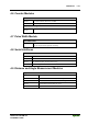
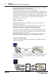
Fig. 5-3: Connection of a Node by means of a Hub with Parallel cables
g012908d
An ETHERNET switch is a device that allows all connected devices to
transmit and receive data with each other. The switch can also be viewed as a
“data traffic cop” where the hub “polices” the data coming in and going out of
the individual ports, so the data will only be transmitted to the required node.
WAGO recommends using a switch rather then a hub, this will allow for a
more deterministic architecture.
Attention
The cable length between the node and the hub cannot be longer than 100 m
(328 ft.) without adding signal conditioning systems (i.e., repeaters). Various
possibilities are described in the ETHERNET standard for networks covering
larger distances.
5.2.2 Network Topologies
In the case of 10Base-T, or 100BaseTX several stations (nodes) are connected
using a star topology according to the 10Base-T ETHERNET Standard.
Therefore, this manual only deals with the star topology, and the tree topology
for larger networks in more detail.
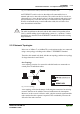
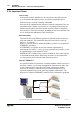
Star Topology
A star topology consists of a network in which all nodes are connected to a
central point via individual cables.
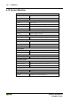
Fig. 5-4: Star Topology G012903e
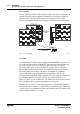
A star topology offers the advantage of allowing the extension of an existing
network. Stations can be added or removed without network interruption.
Moreover, in the event of a defective cable, only the network segment and the
node connected to this segment is impaired. This considerably increases the
fail-safe of the entire network.