
Technical data


42 • Fieldbus Controller 750-841
Hardware
WAGO-I/O-SYSTEM 750
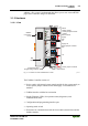
ETHERNET TCP/IP
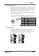
LED Color Meaning
LINK green Link to a physical network exists
MS red/green The ‚MS‘-LED indicates the state of the node (Module State)
NS red/green The ‚NS‘-LED indicates the state of the network (Network State)
TxD/RxD green Data exchange taking place
IO red /green
/ orange
The 'I/O'-LED indicates the operation of the node and signals faults
encountered
USR red /green
/ orange
The 'USR' LED can be controlled by a user program in a controller
A green Status of the operating voltage – system
B or C green Status of the operating voltage – power jumper contacts
(LED position is manufacturing dependent)
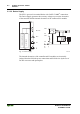
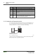
3.1.2.5 Configuration and Programming Interface
The Configuration and Programming Interface port is located behind a cover
flap. This communications port can be use with WAGO-I/O-CHECK and
WAGO-I/O-PRO CAA, as well as for firmware downloading.
Configuration and
programming interface
Fig. 3-2: Configuration Interface g01xx07e
A WAGO 750-920 Communication Cable is used to connect the 4 pin male
header and with a PC’s 9-pin RS232 interface.