
Technical data

Fieldbus Controller 750-841 • 59
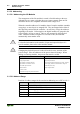
Process Image
WAGO-I/O-SYSTEM 750
ETHERNET TCP/IP
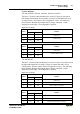
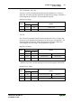
Input and Output Process Image
Byte Destination
Offset
High Byte Low Byte
Remark
0 - C0/S0 Control/Status byte of Channel 1
1 D1 D0 Data Value of Channel 1
2 - C1/S1 Control/Status byte of Channel 2
3 D3 D2 Data Value of Channel 2
Serial Interface Modules with alternative Data Format
750-650, /000-002, -004, -006, -007, -008, -009, -010, -011, -012, -013, -017,
-020, -021, -023
750-651, /000-002, -003, -004, -006
750-653, /000-001, -002, -005, -007, -008, -010
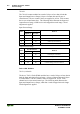
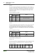
The above Serial Interface Modules have a total of 4 bytes of user data in both
the Input and Output Process Image (3 bytes of serial data and 1 byte of
control/status). The following table illustrates the Input and Output Process
Image, which has 2 words mapped into each image. Word alignment is
applied.
Input and Output Process Image
Byte Destination
Offset
High Byte Low Byte
Remark
0 D0 C/S Data byte Handshake
1 D2 D1 Data bytes
Serial Interface Modules with Standard Data Format
750-650/000-001, -014, -015, -016, -018, -019, -022
750-651/000-001, -007
750-653/000-006, -009, -011, -018
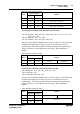
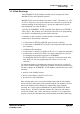
The above Serial Interface Modules have a total of 6 bytes of user data in both
the Input and Output Process Image (5 bytes of serial data and 1 byte of
control/status). The following table illustrates the Input and Output Process
Image, which has 3 words mapped into each image. Word alignment is
applied.
Input and Output Process Image
Byte Destination
Offset
High Byte Low Byte
Remark
0 D0 C/S Data byte Control/Status byte
1D2 D1
2D4 D3
Data bytes