
Technical data


Data exchange module 750-654
:$*2Ç,2 Ç6<67(0
5
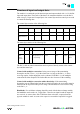
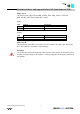
Structure of the in- and output data for Profibus (from firmware WH)
The ID 179 (hex: 0xB3), (
Data consistence over 4 Byte) is used.
Outputs
Byte Description
D0 Output byte0
D1 Output byte1
D2 Output byte2
D3 Output byte3
Inputs
Byte Description
D0 Input byte0
D1 Input byte1
D2 Input byte2
D3 Input byte3
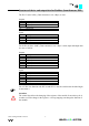
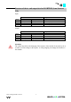
For the ID 188 (hex.: 0xBC), Data consistence over 6 Byte is used, input and output data
are now as follows:
Outputs
Byte Description
D0 Control byte
D1 Output byte0
D2 Output byte1
D3 Output byte4
D4 Output byte2
D5 Output byte3
Inputs
Byte Description
D0 Statusbyte
D1 Input byte0
D2 Input byte1
D3 Input byte4
D4 Input byte2
D5 Input byte3
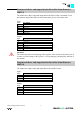
For a S7 PLC the function code SFC14 and SFC15 must be used because the data length
is more than 4.
Attention:
The control byte allows the changing of the registers of the module. It must always be 0
in order to avoid a change in the registers. A wrong mapping can change the function of
the module!