
Users Manual

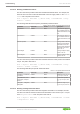
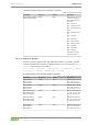
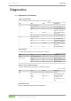
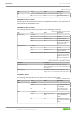
Table Of Contents
- Table of Contents
- 1 Provisions
- 2 Safety
- 3 Overview
- 4 Properties
- 5 Functions
- 6 Planning
- 7 Transport and Storage
- 8 Installation and Removal
- 9 Connection
- 10 Commissioning
- 10.1 Setting an IP Address
- 10.2 Parameterization
- 10.2.1 PROFINET
- 10.2.2 WAGO Webserver I/O Field
- 10.2.2.1 Opening WAGO Webserver I/O Field
- 10.2.2.2 WAGO Webserver I/O Field User Interface
- 10.2.2.3 Opening the Product Information via WAGO Webserver I/O Field
- 10.2.2.3.1 Displaying Port Information
- 10.2.2.3.2 Displaying Measured Values and Information on Connected IO-Link Devices
- 10.2.2.3.3 Displaying Port Status Information
- 10.2.2.3.4 State
- 10.2.2.3.5 Quality
- 10.2.2.3.6 Revision ID
- 10.2.2.3.7 Baud Rate
- 10.2.2.3.8 Cycle Time
- 10.2.2.3.9 Input Data Length
- 10.2.2.3.10 Output Data Length
- 10.2.2.3.11 Vendor ID
- 10.2.2.3.12 Device ID
- 10.2.2.3.13 Displaying Process Data
- 10.2.2.4 Parameterizing the Product via WAGO Webserver I/O Field
- 10.2.2.4.1 Accessing a Connected IO-Link Device
- 10.2.2.4.2 Configuring Ports
- 10.2.2.4.3 Configuring IP Parameters
- 10.2.2.4.4 Storing Maintenance Information
- 10.2.2.4.5 Updating Firmware
- 10.2.2.4.6 Resetsetting the Module to the Factory Settings
- 10.2.2.4.7 Configure Bluetooth
- 10.2.2.4.8 Logging Users on and off and Managing Them
- 10.2.2.4.9 Forcing Digital Inputs and Outputs
- 10.2.2.4.10 Forcing IO-Link ports
- 10.2.3 WAGO IO-Link Configurator
- 10.2.3.1 System Requirements
- 10.2.3.2 Launching WAGO IO-Link Configurator
- 10.2.3.3 WAGO IO-Link Configurator User Interface
- 10.2.3.4 Parameterizing the Product with WAGO IO-Link Configurator
- 10.2.4 WAGO I/O Field app
- 10.2.5 OPC UA Server
- 11 Diagnostics
- 12 Service
- 13 Decommissioning
- 14 Appendix
- List of Tables
- List of Figures

765-4102/0100-0000 Diagnostics
Product manual | Version: 2.1.0 129
8PORT IOL-B FLD PN DC 24V 2.0A
11Diagnostics
11.1 Diagnostics via Indicators
Supply Voltage Status
The 1L and 2L LEDs indicate the status of the supply voltages.
Table 74: Supply Voltage Status, 1L and 2L
LED Color State Description
1L Duo LED, red/green
Green On 1L supply voltage ok
Red On 1L undervoltage (voltage
between 11V and 18V)
Red Flashing 1L overvoltage (voltage
above 30V)
Off Off No 1L supply voltage
2L Duo LED, red/green
Green On 2L supply voltage ok
Red On 2L undervoltage (voltage
between 11V and 18V)
Red Flashing 2L overvoltage (voltage
above 30V)
Off Off No 2L supply voltage
System Status
The SYS LED indicates the status of the system (product).
Table 75: System Status
LED Color State Description
SYS
(system status)
Duo LED, yellow/green
Green On System status: OK
Yellow On Firmware update is active
Off Off No power supply
Status of the Field-Side Functions
The FLD LED indicates the status of the field-side functions.
Table 76: Field LED
LED Color State Description
FLD Duo LED, green/yellow (yellow = simultaneously red and green)
Green On Normal operating state
Green Flashing (1Hz) Force mode is active
Yellow On Configuration error
Off Off Non-operational; no volt-
age
Application Status
The APL LED indicates the status of the application.