
Users Manual

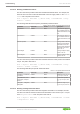
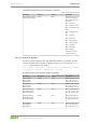
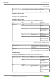
Table Of Contents
- Table of Contents
- 1 Provisions
- 2 Safety
- 3 Overview
- 4 Properties
- 5 Functions
- 6 Planning
- 7 Transport and Storage
- 8 Installation and Removal
- 9 Connection
- 10 Commissioning
- 10.1 Setting an IP Address
- 10.2 Parameterization
- 10.2.1 PROFINET
- 10.2.2 WAGO Webserver I/O Field
- 10.2.2.1 Opening WAGO Webserver I/O Field
- 10.2.2.2 WAGO Webserver I/O Field User Interface
- 10.2.2.3 Opening the Product Information via WAGO Webserver I/O Field
- 10.2.2.3.1 Displaying Port Information
- 10.2.2.3.2 Displaying Measured Values and Information on Connected IO-Link Devices
- 10.2.2.3.3 Displaying Port Status Information
- 10.2.2.3.4 State
- 10.2.2.3.5 Quality
- 10.2.2.3.6 Revision ID
- 10.2.2.3.7 Baud Rate
- 10.2.2.3.8 Cycle Time
- 10.2.2.3.9 Input Data Length
- 10.2.2.3.10 Output Data Length
- 10.2.2.3.11 Vendor ID
- 10.2.2.3.12 Device ID
- 10.2.2.3.13 Displaying Process Data
- 10.2.2.4 Parameterizing the Product via WAGO Webserver I/O Field
- 10.2.2.4.1 Accessing a Connected IO-Link Device
- 10.2.2.4.2 Configuring Ports
- 10.2.2.4.3 Configuring IP Parameters
- 10.2.2.4.4 Storing Maintenance Information
- 10.2.2.4.5 Updating Firmware
- 10.2.2.4.6 Resetsetting the Module to the Factory Settings
- 10.2.2.4.7 Configure Bluetooth
- 10.2.2.4.8 Logging Users on and off and Managing Them
- 10.2.2.4.9 Forcing Digital Inputs and Outputs
- 10.2.2.4.10 Forcing IO-Link ports
- 10.2.3 WAGO IO-Link Configurator
- 10.2.3.1 System Requirements
- 10.2.3.2 Launching WAGO IO-Link Configurator
- 10.2.3.3 WAGO IO-Link Configurator User Interface
- 10.2.3.4 Parameterizing the Product with WAGO IO-Link Configurator
- 10.2.4 WAGO I/O Field app
- 10.2.5 OPC UA Server
- 11 Diagnostics
- 12 Service
- 13 Decommissioning
- 14 Appendix
- List of Tables
- List of Figures
765-4102/0100-0000Diagnostics
130 Product manual | Version: 2.1.0
8PORT IOL-B FLD PN DC 24V 2.0A
Table 77: APL LED
LED Color State Description
APL Duo LED, red/green/yellow (yellow = simultaneously red and green)
Off Off LED without function
PROFINET IO-Device Status
The BF and SF LEDs indicate the status of the PROFINET IO-Device. The LNK and ACT
LEDs indicate the ETHERNET status.
PROFINET IO-Device Status
The following table describes the LED states of the PROFINET IO-Device.
Table 78: PROFINET IO-Device Status
LED Color State Description
BF (bus error) Red LED
Off Off No error
Red Flashing (2Hz) No data exchange
Red On No configuration, slow
physical connection or no
physical connection
SF (system error) Red LED
Off Off No error
Red Flashing (1Hz, 3s) DCP signal service is trig-
gered via the bus
Red On Watchdog timeout; chan-
nel, generic or extended
diagnostics present; sys-
tem error; forcing active
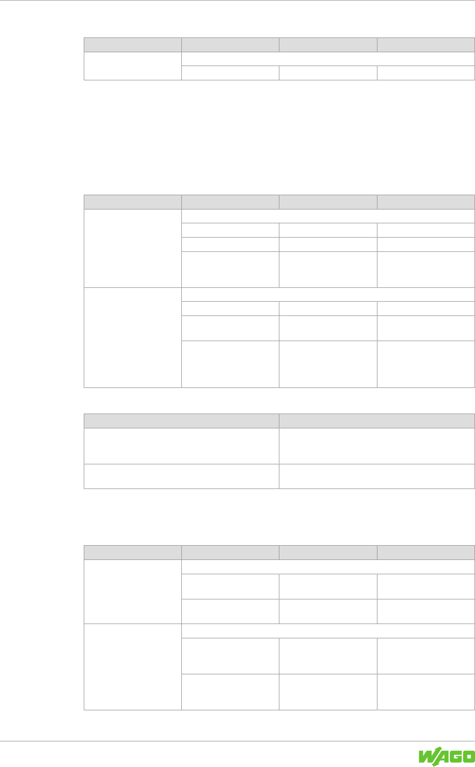
Table 79: LED states – PROFINET IO-Device
LED State Description
Flashing (1Hz, 3s) The indicator switches on and off for 3 second in
phases at a frequency of 1Hz: on for 500ms and then
off for 500ms
Flashing (2Hz) The indicator switches on and off in phases at a fre-
quency of 2Hz: on for 250ms and then off for 250ms
ETHERNET Status
The following table describes the LED states of the link and activity LEDs.
Table 80: ETHERNET Status
LED Color State Description
LNK LED green
Green On The module is connected
to ETHERNET
Off Off The module is not con-
nected to ETHERNET
ACT LED yellow
Yellow Flickering (load-depen-
dent)
The module is sending/re-
ceiving ETHERNET
frames
Off Off The module is not send-
ing/receiving ETHERNET
frames