
Users Manual
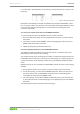
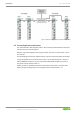
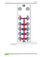
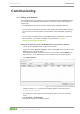
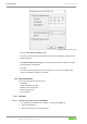
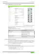
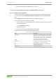
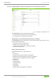
Table Of Contents
- Table of Contents
- 1 Provisions
- 2 Safety
- 3 Overview
- 4 Properties
- 5 Functions
- 6 Planning
- 7 Transport and Storage
- 8 Installation and Removal
- 9 Connection
- 10 Commissioning
- 10.1 Setting an IP Address
- 10.2 Parameterization
- 10.2.1 PROFINET
- 10.2.2 WAGO Webserver I/O Field
- 10.2.2.1 Opening WAGO Webserver I/O Field
- 10.2.2.2 WAGO Webserver I/O Field User Interface
- 10.2.2.3 Opening the Product Information via WAGO Webserver I/O Field
- 10.2.2.3.1 Displaying Port Information
- 10.2.2.3.2 Displaying Measured Values and Information on Connected IO-Link Devices
- 10.2.2.3.3 Displaying Port Status Information
- 10.2.2.3.4 State
- 10.2.2.3.5 Quality
- 10.2.2.3.6 Revision ID
- 10.2.2.3.7 Baud Rate
- 10.2.2.3.8 Cycle Time
- 10.2.2.3.9 Input Data Length
- 10.2.2.3.10 Output Data Length
- 10.2.2.3.11 Vendor ID
- 10.2.2.3.12 Device ID
- 10.2.2.3.13 Displaying Process Data
- 10.2.2.4 Parameterizing the Product via WAGO Webserver I/O Field
- 10.2.2.4.1 Accessing a Connected IO-Link Device
- 10.2.2.4.2 Configuring Ports
- 10.2.2.4.3 Configuring IP Parameters
- 10.2.2.4.4 Storing Maintenance Information
- 10.2.2.4.5 Updating Firmware
- 10.2.2.4.6 Resetsetting the Module to the Factory Settings
- 10.2.2.4.7 Configure Bluetooth
- 10.2.2.4.8 Logging Users on and off and Managing Them
- 10.2.2.4.9 Forcing Digital Inputs and Outputs
- 10.2.2.4.10 Forcing IO-Link ports
- 10.2.3 WAGO IO-Link Configurator
- 10.2.3.1 System Requirements
- 10.2.3.2 Launching WAGO IO-Link Configurator
- 10.2.3.3 WAGO IO-Link Configurator User Interface
- 10.2.3.4 Parameterizing the Product with WAGO IO-Link Configurator
- 10.2.4 WAGO I/O Field app
- 10.2.5 OPC UA Server
- 11 Diagnostics
- 12 Service
- 13 Decommissioning
- 14 Appendix
- List of Tables
- List of Figures

765-4102/0100-0000 Connection
Product manual | Version: 2.1.0 61
8PORT IOL-B FLD PN DC 24V 2.0A
For a cable that is pre-assembled on one end only, proceed as follows to connect it to an
RJ45 plug:
Figure8: RJ45 Pin Assignment
Because the Auto MDI(X) functionality is enabled for the respective ETHERNET connec-
tion, a crossover cable is not necessary. This functionality automatically detects the direc-
tion for sending data and receiving data, so it is irrelevant which cable type is used
(crossed or uncrossed).
Connecting an Individual Product to an ETHERNET Network
To connect the product to the ETHERNET network, proceed as follows:
1. Disconnect the power supply from the equipment parts on which you have mounted
the module.
2. Connect the product to the ETHERNET network by plugging the socket of the ETH-
ERNET cable onto the X21 connection.
3. Tighten the plug using the knurled-head screw.
Connecting Multiple Products to One ETHERNET Network
The fieldbus module of the WAGO I/O System Field has two connections with an inte-
grated switch to allow wiring of a line topology.
The network topology in the following figure consists of a mixed star and line topology. An
ETHERNET switch is required in order to set up a star topology or a mixed topology. The
number of products in a star topology is limited only by the IEEE 802.3 Ethernet specifi-
cation.
Multiple products can be connected to the ETHERNET network as shown in the following
example:
1. De-energize the section of your system to which you wish to mount the product.
2. For the star topology, connect each ETHERNET cable (W1, W2) to port X21 of one
765 Series product and one ETHERNET switch as shown in the following figure.
Then tighten the plugs of the ETHERNET cable.
3. For a line topology, connect the ETHERNET cables (W3, W4) to ports X21 and X22
on the product as shown in the following figure. Then tighten the plugs of the ETHER-
NET cable.
The following figure shows a mixed star and line topology: