OWNER’S MANUAL Safety, Assembly, Operating, and Maintenance Instructions Model MS (13 HP) ™ Please Read and Save These Instructions For Safety, Read All Safety and Operation Instructions Prior to Operating Machine Effective Date: 01-15-05 P/N 5000-16
Foreword Thank you. . .for purchasing a Walker mower. Every effort has been made to provide you with the most reliable mower on the market, and we are sure you will be among our many satisfied customers. If for any reason this product does not perform to your expectations, please contact us at (970) 221-5614. Every customer is important to us. Your satisfaction is our goal. Please. . .
Table of Contents General Information ________________ 1 Operating Instructions_____________ HIGHLIGHTED INFORMATION _____________ 1 GLOSSARY ____________________________ 1 IDENTIFYING NUMBER LOCATIONS________ 1 ENGINE SERIAL NUMBER LOCATION ______ 2 SERVICING OF ENGINE AND DRIVETRAIN COMPONENTS__________ 2 CONTROL IDENTIFICATION, LOCATION, AND FUNCTION _____________ Ignition Switch _______________________ Engine Choke________________________ Engine Throttle ______________________ Forward Speed Control (
Table of Contents Maintenance Instructions __________ 40 MAINTENANCE SCHEDULE CHART _______ 40 IMPORTANT TIPS FOR CARE OF THE KAWASAKI ENGINE ____________________ 41 Fuel System _________________________ 41 Starting _____________________________ 41 Cooling System ______________________ 41 Air Cleaner __________________________ 41 Oil _________________________________ 41 LUBRICATION _________________________ 42 Engine Oil ___________________________ 42 Engine Break-In Oil __________________ 42 Checking Engin
General Information HIGHLIGHTED INFORMATION Walker Manufacturing recommends that any service requiring special training or tools be performed by an authorized Walker Mower Dealer. There are several general practices to be aware of in the area of safety. Most accidents associated with the operation or maintenance of a Walker Mower are caused by disregarding basic safety precautions or specific warnings. Such accidents, in most cases, can be prevented by being aware of the dangers present.
General Information Serial Number Tractor Serial Number Location SERVICING OF ENGINE AND DRIVETRAIN COMPONENTS The detailed servicing and repair of the engine, hydrostatic transmission and gearboxes are not covered in this manual. Only routine maintenance and general service instructions are provided. For the service of these components during the limited warranty period, it is important to find a local, authorized servicing agent of the component manufacturer.
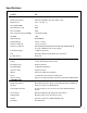
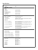
Specifications MODEL MS ENGINE Manufacturer/Model Kawasaki, FE 400D, 1 Cyl. OHV (Air-Cooled) Displacement 24.5 cu. in. (401 cc) HP (@ 3600 RPM) 13.0 Max. RPM (No Load) 4000 Governed RPM 3600 Max. Torque [ft-lb (N⋅ m) @ RPM] 19.5 (26.4) @ 2500 Idle RPM 1300 Spark Plug Type NGK BPR5ES Spark Plug Gap .030 in. (.75 mm) Crankcase Capacity 1.35 qts (1.
Specifications MODEL MS TRANSMISSION (continued) Transmission Fluid Factory Service Mobil 1 Synthetic Motor Oil (15W-50) Transmission Fluid Capacity 1 qt (1 liter) Transmission Cooling Cooling Fan Mounted on Drive Pulley Ground Travel Speed Forward m.p.h. (km/h) Reverse m.p.h.
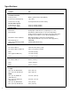
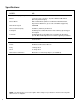
Specifications MODEL MS DIMENSIONS (continued) Height SD Model 37-1/2 in. (95 cm) GHS Model 44-1/2 in. (112 cm) Wheel Base (Tractor) 42-1/4 in. (107 cm) Tread Width (Tractor) Standard Tires 28-1/4 in. (72 cm) Optional Tires 29-3/4 in. (76 cm) MOWER DECK Width of Cut SD/GHS 36 or 42 in. (91 or 107 cm) Cutting Height 1 to 4 in. (3 to 10 cm) Height Adjustment 7 Positions - 1/2 in. (1 cm) Increment Hitch Pins Installed in Multi-Position Deck Support Blade Size 36 in. (91 cm) SD Model 20 in.
Specifications MODEL MS GHS SYSTEM (Optional) Blower 3 1/2 x 9 x 1/4 in. (9 x 23 x 1 cm) Three-Blade Paddle Wheel (Driven by Mower Engine) Blower Brake Belt Scrubber Brake (Works in Combination with PTO Clutch, Stops Blower within Five (5) Seconds of PTO Disengagement) Max. Blower Speed 3600 RPM Grass Catcher Capacity 63 Gallons (238 liters)/6.
Component Identification NOTE: Control Identification shown in Operating Instructions section. Grass Handling System 6.
Component Identification Catcher Door Gas Spring Protective Cover Removable Grass Catcher Screen (Not Visible) Catcher Door Gas Spring Catcher Exhaust Deflector Catcher Door Catcher Lift/ Dump Handle Catcher Door Handle Anti-Scuff Rollers Left Hand Drive Wheel Oil Filter Fuel Filter Fuel Shut-off Valve Rotating Engine Screen Tailwheel Fork and Wheel Rear View and Left Side View 8
Component Identification Air Cleaner Dust Cup Air Cleaner Rubber Bumper Body Support Air Restriction Indicator Air Intake Hose Fuel Tank Carburetor Fuel Tank Cap Fuel Level Indicator Starter Solenoid (Not Shown) Muffler GHS Blower Tractor PTO Gearbox RH Transmission Lockout Lever RH Hydrostatic Transmission Positive (+) Battery Cable LH Hydrostatic Transmission Negative (-) Battery Cable Battery Neutral Safety Switch LH Transmission Lockout Lever Top View (Body Raised) 9
Safety Instructions Pay particular attention to any information labeled DANGER, WARNING, CAUTION, IMPORTANT, and NOTE in this manual. When you see the Safety Alert Symbol ( ), read, understand, and follow the instructions. Failure to comply with safety instructions may result in personal injury.
Safety Instructions 6. 7. 8. 9. Do not wear loose fitting clothing that could get caught in moving parts. Do not operate this machine while wearing shorts; always wear adequate protective clothing, including long pants. Wearing safety glasses, safety shoes, and a helmet is advisable and required by some local ordinances and insurance regulations. Prolonged exposure to loud noise can cause impairment or loss of hearing.
Safety Instructions 9. Watch for holes, rocks, and roots in the terrain and for other hidden hazards. When mowing tall grass, mow higher than desired to expose any hidden obstacles. Then, clean the area and mow to the desired height. 10. Avoid sudden starts or stops. Before backing the machine up, look to the rear to be sure no one is behind the machine. Watch carefully for traffic when crossing or working near roadways. 17. For GHS equipped models, use care when closing the grass catcher door.
Safety Instructions 3. Keep all nuts, bolts, and screws tight to ensure the machine is in a safe, working condition. Check the blade mounting nuts frequently, making sure they are tight. c. Keep sparks, flames, and smoking materials away from the battery at all times. To avoid sparks, use care when removing battery cables from posts. 4. Perform only maintenance instructions described in this manual. Unauthorized maintenance operations or machine modifications may result in unsafe operating conditions.
Safety Instructions SAFETY, CONTROL, AND INSTRUCTION DECALS Safety, Control, and Instruction Decals are installed on the machine; if any are missing, illegible, or damaged, a replacement should be ordered and installed before putting the machine into operation. The Decal Part Number is listed below and in the Parts Manual.
Safety Instructions SAFETY, CONTROL, AND INSTRUCTION DECALS Safety, Control, and Instruction Decals are installed on the machine; if any are missing, illegible, or damaged, a replacement should be ordered and installed before putting the machine into operation. The Decal Part Number is listed below and in the Parts Manual.
Assembly Instructions SETUP INSTRUCTIONS Dry Battery Service Walker Mowers are shipped partially assembled. After uncrating the tractor and mower deck, initial setup is required. DANGER Activating a battery can be dangerous. The battery should be taken to a reliable service station, battery store, or power equipment dealer where a trained technician can activate the battery safely. DO NOT attempt to activate the battery unless you are experienced in battery service work.
Assembly Instructions Battery Charging Battery Clamp Secured by Wing Nuts DANGER (+) Battery Cable Connection BATTERIES PRODUCE EXPLOSIVE GASES • Charge the battery in a well-ventilated area, so that gases produced while charging can dissipate. • Keep sparks, flames, and smoking materials away from the battery at all times.
Assembly Instructions Deck Discharge Shield Installation (Side Discharge Models Only) Grease Fitting Locations Attach the deck side discharge shield by positioning the shield hinge lug in front of the deck mount and fastening with two (2) 3/8-16 x 1-1/4 in. bolts, 3/8-16 ESNA nuts, and 3/8 in. wave spring washers. The wave washers fit between the two hinging surfaces. Tighten the nuts until the shield moves freely but is not loose.
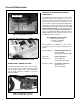
Assembly Instructions Grease Deck Support Arms Attach Spring PTO Connection Arrows on Shaft and Tube (used to align when sliding together) Roller Wheels Mower Deck Installation/PTO Shaft Connection Tilt-Up Spring and Roller Wheel Installation on Rear Discharge Deck Mower Deck Installation on Tractor 5. Install the hitch pin through the hole on the end of each support arm to lock the deck in place (refer to Deck Counterweight Spring Installation photo).
Assembly Instructions Spring Tension Adjustment Nut Located Under Lower Spring Hook (not visible) Counterweight Springs Clip Onto Body With Body Tilted Up Hitch Pins Lock Deck On Support Arms Deck Counterweight Spring Installation 20 6. Raise mower body (instead of lifting the front of deck) and clip the counterweight springs to the receptacle on front of body. Lower the body to tension the springs. (Refer to Deck Counterweight Spring Installation photo.) 7.
Assembly Instructions Deck Leveling 1. 2. Check the side-to-side level. Rotate each blade sideways and measure the distance from blade tip to ground on each side. If measurements vary more than 1/8 in. (3 mm), add a washer shim under the deck support pins on the low side to level the deck. 3. Check the front-to-rear level. Rotate the blades to point forward. Measure the distance from blade tip to ground on the front and rear. The rear of the blade should be 1/8 to 1/4 in.
Assembly Instructions PREOPERATING CHECKLIST Before operating the mower for the first time, and as a routine before daily operations, it is important to make sure the mower is properly prepared and ready for operation. The following is a list of items to be checked. (For a mower with frequent operation, some of these items will not need to be checked every day, but the operator should be aware of the condition of each.) For proper fuel and lubricants refer to Specifications.
Assembly Instructions INSPECT THREE (3) DRIVE BELTS CAUTION Engine, PTO, and Hydrostatic Ground Drive. CHECK HYDROSTATIC TRANSMISSION OIL LEVEL Refer to LUBRICATION for Checking Hydrostatic Transmission Fluid Level in Maintenance Instructions.
Operating Instructions CONTROL IDENTIFICATION, LOCATION, AND FUNCTION CAUTION Before operating the mower, become familiar with the location and function of all operator controls. Knowing the location, function, and operation of these controls is important for safe and efficient operation of the mower. Ignition Switch The ignition switch is located on the right front of the body and is used to start and stop the engine.
Operating Instructions Engine Throttle Steering Levers The throttle control lever (red knob) is located on the left side of the seat and is used to control engine speed. Moving the lever forward toward the FAST position increases engine speed; moving it backward toward the IDLE position decreases engine speed. Each drive wheel is controlled by its own independent steering lever, for both steering function and FORWARD/REVERSE motion.
Operating Instructions Transmission Lockout Levers The transmission lockout levers disengage the hydrostatic transmissons. By lifting the lever on top of the transmission and locking it into place with the lockout cam, the hydrostatic transmissions are released to permit freewheeling. By releasing the cam and lowering the lever, the transmissions are engaged for normal operation. The transmission lever in the LOCKOUT position is used to enable moving the machine without the engine running (e.g.
Operating Instructions The Forward Speed Control also Establishes the Neutral-Park Position of the Steering Levers LEFT WHEEL STEERING LEVER RIGHT WHEEL STEERING LEVER FORWARD SPEED CONTROL LEVER (FSC) Full Forward Ground Speed Position Forward Position (No Control Change) Intermediate Ground Speed Position Neutral-Park Position Reverse Drive Wheel Motion Position Neutral-Park Position PARKING BRAKE Engaged Position Disengaged Position Fast Throttle Position Disengaged Position Idle Position THR
Operating Instructions STARTING THE ENGINE IMPORTANT: DO NOT crank the engine continuously for more than 10 seconds at a time. If the engine does not start, turn the key to the OFF position and allow a 60 second cool-down period between starting attempts. Failure to follow these guidelines can damage the starter motor and shorten battery life. CAUTION Before operating the mower, read and understand all Safety Instructions and Operating Instructions. 3.
Operating Instructions WARNING Beginning Recommendations are: ♦ Learn operation of the mower in an open area away from buildings, fences, and obstructions. Learn operation on flat ground BEFORE operating on slopes. In case either of the transmission drive belts break during operation, and if the machine is on a slope, the machine will freewheel down the slope. To maintain control, immediately (1) Release the steering levers and simultaneously (2) Move the FSC to the NEUTRAL-PARK position.
Operating Instructions NOTE: Smooth action on the steering levers will produce smooth mower operation. Remember to keep the engine and ground speed slow until learning the control response. 4. 5. The FSC may be adjusted forward for faster ground speed and backward for slower ground speed. When mowing, ground speed should be adjusted to match the load on the cutter blades, i.e., as the engine pulls down in heavy cutting, pull back on the FSC lever to reduce ground speed.
Operating Instructions STOPPING THE MACHINE 1. Slow the engine to idle; put the throttle in the IDLE position. 2. Pull the steering levers to the NEUTRAL-PARK position and then move the FSC lever backward to the NEUTRAL-PARK position. 3. Disengage the blade clutch. IMPORTANT: DO NOT disengage the blade clutch with high engine speed (above 1/2 throttle) since the brake action on the blade drive will cause premature wear of the PTO Drive Belt.
Operating Instructions TRANSMISSION LOCKOUT Lockout Lever IMPORTANT: DO NOT TOW this mower with the transmission lockout engaged. Towing can produce excessive internal pressure and damage the transmission. To move the mower with the engine NOT running (dead battery, maintenance, etc.), the hydrostatic transmissions are unlocked (released). Plunger Released 1. Raise the body. 2. Lift the transmission lockout lever on both the RH and LH transmissions and secure into place with the locking cam. 3.
Operating Instructions • Make sure the mower is leveled properly for a smooth cut. Refer to Deck Leveling in Assembly Instructions. • Use an alternating stripe mowing pattern for best appearance and vary the direction of the stripe each time the grass is mowed to avoid wear patterns in the grass. Maximum Recommended Side Slope - Do Not Operate on Steep Slopes • Avoid damage to the grass by slipping and skidding of the drive tires.
Operating Instructions GRASS HANDLING SYSTEM (GHS) GHS Model Only Exhaust Screen (Removable) Catcher Door Safety Latch Grass-Pak® Vane Switch Exhaust Deflector Powerfil ® Drive Motor Actuator Rod “Full” Signal Horn PTO Clutch Catcher Door Catcher Door Spring Shear Pin PTO and Blade Gear Drive Grass Catcher Shear Bolt Dump Handle Powerfil ® Delivery Spout Body Chute Assembly Blower Deck Discharge Chute Rear Discharge Mower Deck GHS Flow and Components 34
Operating Instructions General Information The Grass Handling System (GHS) consists of a rear discharge mower deck connected to a 9 in. (23 cm) blower and a rear mounted grass catcher with 6.7 bushel (238 liters) capacity. The GHS blower operates any time the mower blade clutch is engaged and moves grass through the rear discharge deck chute into the grass catcher. Blower airflow is exhausted out the back of the grass catcher, through a filtering screen.
Operating Instructions Clogging Checklist • Check the amount of flat section remaining at In case of clogging, there will be a distinct change in the sound of the blower, i.e., the blower sound will stop. Also, the mower deck will begin to leave a trail of grass clippings. When this occurs, stop the engine, disconnect the spark plug wire, and make sure all movement has stopped before attempting to unclog. blade tip. This is the area that is ground away (removed) when the blades are sharpened.
Operating Instructions • Check that the openings in the air exhaust screen in the grass catcher are not plugged. If the screen is clogged, refer to Cleaning the GHS Exhaust Screen in this section. Remember, anything that restricts airflow or material flow along the entire path from the mower deck to the grass catcher can cause clogging. Using the Tilt-Up Deck Refer to CLEANING of Grass Buildup in Mower Housing in Maintenance Instructions.
Operating Instructions Dumping the Catcher Using the Dump Bag For dumping, the catcher either tailgate dumps into a disposal area or dumps into the optional dump bag. The dump bag is a reusable nylon fabric bag designed to conveniently move grass clippings from the catcher to a remote disposal area or container. 1. Tailgate Dumping 1. 2. Tilt the catcher back to dump by lifting on the handle on the front of the catcher. 3. Lower the catcher smoothly down to the normal operating position.
Operating Instructions Tailgate Door Handle Catcher Dump Handle Hook Bag on Bumper Positioning Dump Bag on Catcher 6. Close the door by holding the door handle with the left hand and releasing the safety latch on the door hinge mechanism with the right hand. The safety latch is released by pressing in on the top of the latch. Then, the door should close smoothly with the assistance of the gas springs.
CAUTION Maintenance Instructions Maintenance procedures requiring special training or tools should be performed by a trained technician. MAINTENANCE SCHEDULE CHART - RECOMMENDED SERVICE INTERVALS - MODEL MS Service Item 25 Hours 50 Hours 100 Hours Yearly Every 2Years Ref.
Maintenance Instructions KAWASAKI TIPS IMPORTANT TIPS FOR CARE OF THE KAWASAKI ENGINE Air Cleaner Fuel System market elements may not seal in the air cleaner housing, allowing dirt to enter the engine. Also, aftermarket filters often skimp on the filtration media and require more frequent cleaning and replacement (see instructions below). • Fuel must be clean - free from water, dirt, and organic material.
Maintenance Instructions LUBRICATION LUBRICATION IMPORTANT: DO NOT operate engine without sufficient oil supply in the crankcase. DO NOT operate with oil level below the LOW (L) mark or above the FULL (H) mark on the dipstick. WARNING DO NOT attempt to lubricate the machine with the engine running. Disengage the PTO clutch, shut off the machine, and remove the ignition key. NOT SCREWED IN Filler Plug Proper lubrication is an important maintenance procedure.
Maintenance Instructions Changing Engine Crankcase Oil/Oil Filter LUBRICATION 7. Install the new oil filter on the engine. Turn the oil filter clockwise until the rubber gasket contacts the sealing surface, then tighten the filter an additional 3/4 turn. 8. Reinstall the drain plug. Make sure it is tightened to 16.5 ft-lb (23 N·m). 9. Fill the crankcase (through the dipstick opening) with oil using only crankcase lubricants supplied by the engine manufacturer.
Maintenance Instructions Ident No.
Maintenance Instructions 1 2 3 LUBRICATION 2 1 4 4 10 10 5 6 7 6 6 7 6 8 8 9 9 31 14 15 11 15 13 12 11 27 & 34 16 19 12 28 & 33 17 18 19 18 20 21 13 32 31 22 30 23 29 23 25 24 25 22 28 24 27 26 26 Chassis and Deck Lubrication Points 45
Maintenance Instructions LUBRICATION Mower Deck Gearbox Lubrication The mower deck gearboxes (tee gearbox and blade drive gearboxes) are connected as a unitized assembly, and oil flows freely between them. The gearboxes are permanently lubricated (oil filled) and sealed requiring no scheduled lubrication.
Maintenance Instructions Gear Axle Lubrication • The gear axle oil lubrication is SAE 80W-90 (API GL-5) gear lube. • Check the axle oil level after every 100 hours of operation by removing the oil level plug. If additional oil is needed, remove the breather vent on top of axle and fill until oil is at the level plug. • Change axle oil every 1000 hours or two (2) years.
Maintenance Instructions CLEANING CLEANING Push Button to Reset Indicator After Service Engine Air Cleaner System Donaldson Radialseal™ Air Cleaner A remote mounted Donaldson Radialseal™ air cleaner provides the air filtering function. The paper filter element slides over an outlet tube inside the air cleaner canister with radial sealing action, eliminating the possibility of dust leaks due to improper filter installation.
Maintenance Instructions 4. Use a bright light inside the element to inspect for damage. Check the element very carefully for pin holes or other damage that will allow dirt to leak through the paper media. Replace element if necessary. 5. Check the condition and resilience of the radial sealing surface (inside of the open end) of the filter. Replace the filter if any cracks, tears, or other damage to the sealing surface are noted. 6. 8. 9.
Maintenance Instructions IMPORTANT: Service the fuel filter screen only in a clean area where the fuel filter components will not be contaminated by any dust and dirt. CLEANING Rotating Engine Air Intake Screen DANGER Gasoline is extremely flammable and can be highly explosive. To minimize danger: • Use an approved fuel container for gasoline. • DO NOT allow open flames or sparks while performing maintenance or refueling; DO NOT smoke while working with fuel.
Maintenance Instructions 1. 2. 3. Inspect accessible cooling fins and clean with compressed air as needed. If the buildup is excessive, refer to step 2. Remove the spark plug wire and disconnect the breather tube on the valve cover. Do not disconnect the breather tube from the carburetor side. Remove the cylinder head shroud by removing the five (5) bolts, as shown in the Inspect and Clean Cylinder Head Cooling Fins photo.
Maintenance Instructions CAUTION CLEANING 2. Do not operate machine with deck tilt-up pivot joint unlocked. GHS Blower Normally, the GHS blower operates with no maintenance or cleaning. However, when mowing grass that is dirty and damp (especially springtime mowing), a deposit of dirt may accumulate inside the blower housing, causing wear and binding of the blower wheel. When operating in these conditions, inspect the blower frequently for dirt buildup.
CLEANING/ CHECKING/SERVICING Maintenance Instructions Hydrostatic Transmission Cooling Fins CHECKING/SERVICING DANGER Keeping the cooling fins on the hydrostatic transmissions clean and free of obstruction is essential to avoid overheating the transmission fluid and shortening transmission life. The cooling fins should be checked every 100 hours; and cleaned if necessary. To clean the fins, use compressed air and/or a pressure washer.
CHECKING/SERVICING Maintenance Instructions 3. Replace filler caps. IMPORTANT: DO NOT overfill the battery. Electrolyte will overflow through the vent tube onto parts of the machine and WILL result in severe corrosion. Cleaning the Terminals If battery terminals are corroded, remove battery from the mower. Using a wire brush, remove corrosion with a solution of one part baking soda and four parts water. Rinse with clean water.
Maintenance Instructions CHECKING/SERVICING WARNING Intersection Wear Area DO NOT try to straighten a blade that is bent. NEVER weld a broken or cracked blade. ALWAYS replace with a new blade to assure safety. 4. 5. Sharpen at Original 30° Angle If the blade cutting edge is dull or nicked, it should be sharpened. Remove blades for sharpening by grasping the end of the blade using a rag or a thick, padded glove, while loosening and removing the nut, lock washer, and flat washer that mounts the blade.
Maintenance Instructions CHECKING/SERVICING Drive Belts Breaker Points Raise the body and inspect the condition of the three (3) drive belts after every 25 hours of operation -engine, PTO drive, and ground drive. If the belts show signs of cracking or deteriorating, the belts should be replaced. Refer to REPLACING/REPAIRING the Drive Belts in this section. The Kawasaki engine is equipped with electronic ignition. No breaker points, maintenance, or adjustments are necessary with this system.
Maintenance Instructions REPLACING/REPAIRING REPLACING/REPAIRING Drive Belts There are three (3) individual belts on the machine: DANGER • Engine Belt To prevent accidental starting of the engine when replacing parts or repairing the machine, remove the key from the ignition switch and disconnect the spark plug wire. IMPORTANT: ALWAYS use genuine factory replacement parts. Substitute parts CAN result in product malfunction and possible injury to the operator and/or others.
Maintenance Instructions REPLACING/REPAIRING Engine Belt 1. b. To remove the engine belt: a. Roll the belt off the compound pulley and remove the belt. Relax the belt by depressing the springloaded idler arm. Engine Belt Compound Pulley Idler Pulley Push Idler Pulley to Relax Belt Tension Spring Belt Tightener Arm Engine Pulley Engine Belt (Disengaged) 2. Reverse the removal procedure to replace the engine belt.
Maintenance Instructions REPLACING/REPAIRING PTO Drive Belt 1. To remove the PTO drive belt: c. a. Remove the engine belt, as described in previous section. b. Remove 1/4-20 x 3/4 bolt locating belt guide on gearbox pulley and rotate guide to clear belt. 2. Move blade clutch (in direction of engagement) far enough to relax belt scrubber brake without tightening the PTO drive belt. Roll belt off PTO drive pulley and GHS blower pulley (GHS model only).
Maintenance Instructions REPLACING/REPAIRING Ground Drive Belt 1. b. To remove the ground drive belt: a. Slide belt off pulleys, then release the idler. Raise the spring-loaded idler to relax belt. Raise Idler Pulley to Relax Belt Idler Pulley Belt Tightener Arm Tension Spring Hydrostatic Drive Pulley Transmission Drive Pulley Ground Drive Belt Hydrostatic Drive Pulley Ground Drive Belt Assembly (Disengaged) 2. Reverse the procedure to install the ground drive belt.
Maintenance Instructions REPLACING/REPAIRING Blade Overload Shear Bolts PTO Shear Pin The cutting blade is keyed to the blade hub by two (2) shear bolts (10-24 x 5/8 in. stainless steel machine screws). These bolts are designed to shear and protect the blade drive gearbox from damage if the blade encounters a shock load. The PTO drive shaft connection to the deck gearbox has a shear pin to provide shock load protection to the mower deck drive.
Maintenance Instructions Mower Blades WARNING Mower blades are removed and remounted as described in the Sharpen Mower Blades instructions (refer to CHECKING/SERVICING in this section). During the course of sharpening and inspecting mower blades, if there are any of the following conditions of wear or damage, blades should be replaced for reasons of safety and performance of the machine: • An excessive amount of the flat section of the blade has been ground away (removed) when the blade is sharpened.
Maintenance Instructions ADJUSTMENTS ADJUSTMENTS Steering Levers An adjustment range of approximately 3 inches is available on the steering levers - the levers can be adjusted forward or aft depending on the arm length of the operator. The levers can be adjusted by loosening the locknut at the pivot point and the locknut holding the lever in position in the adjustment slide. Adjust levers into most comfortable position and tighten both locknuts.
Maintenance Instructions 1. Position the discharge chute so that it is pointing straight back. a. Turn the ignition switch ON and move the blade clutch to the ENGAGED position (engine not running). b. Open the catcher back door and monitor the spout position (as it oscillates) and move the blade clutch to the DISENGAGED position and turn the ignition switch to the OFF position. WARNING DO NOT test the Grass-Pak® switch with the engine running.
0$,17(1$1&( $1' 6(59,&( 5(&25' 6+((7 DATE SERVICE ITEM ENGINE HOURS BBBBBBBBBBBBBBBBBBBBBBBBBBBBBBBBBBBBBBBBBBBBBBBBBBBBBBBBBBBBBBBBBBBBBBBBBBBBBBBBBBBBBBBBBBBBBBBBBBBBBBBBBBBBBB BBBBBBBBBBBBBBBBBBBBBBBBBBBBBBBBBBBBBBBBBBBBBBBBBBBBBBBBBBBBBBBBBBBBBBBBBBBBBBBBBBBBBBBBBBBBBBBBBBBBBBBBBBBBBB BBBBBBBBBBBBBBBBBBBBBBBBBBBBBBBBBBBBBBBBBBBBBBBBBBBBBBBBBBBBBBBBBBBBBBBBBBBBBBBBBBBBBBBBBBBBBBBBBBBBBBBBBBBBBB BBBBBBBBBBBBBBBBBBBBBBBBBBBBBBBBBBBBBBBBBBBBBBBBBBBBBBBBBBBBBBBBBBBBBBBBBBBBBBBBBBBBBBBBBBBBBBBBBBBBBBBBBBBB
Operator’s Notes 66
LIMITED WARRANTY FOR WALKER COMMERCIAL RIDER MOWER 1. WHAT THIS WARRANTY COVERS, AND FOR HOW LONG: Walker Manufacturing company will, at its option, repair or replace, without charge, any part covered by this warranty which is found to be defective in material and/or workmanship within one (1) year* after date of sale to the original retail purchaser unless the product is used for rental purposes, in which case this warranty is limited to ninety (90) days.
Lwa 99 Sound - Model MS Vibration - Model MS Sound Test Vibration Level Sound test conducted was in accordance with 79/113/EEC and was performed on 22 March 96 under the conditions listed: 0.4g Vibration levels at the operators handles were measured in the vertical, lateral, and longitudinal directions using calibrated vibration test equipment.