OWNER’S MANUAL Safety, Assembly, Operating, and Maintenance Instructions Model MDD (20.9 HP Diesel) ™ Please Read and Save These Instructions For Safety, Read All Safety and Operation Instructions Prior to Operating Machine Effective Date: 12-01-03 P/N 7000-6 Price $5.
Foreword Thank you. . .for purchasing a Walker mower. Every effort has been made to provide you with the most reliable mower on the market, and we are sure you will be among our many satisfied customers. If for any reason this product does not perform to your expectations, please contact us at (970) 221-5614. Every customer is important to us. Your satisfaction is our goal. Please. . .
Table of Contents General Information ________________ 1 Operating Instructions_____________ HIGHLIGHTED INFORMATION _____________ 1 GLOSSARY ____________________________ 1 IDENTIFYING NUMBER LOCATIONS________ 1 ENGINE SERIAL NUMBER LOCATION ______ 2 SERVICING OF ENGINE AND DRIVETRAIN COMPONENTS ______________ 2 CONTROL IDENTIFICATION, LOCATION, AND FUNCTION _____________ Operating Controls ___________________ Engine Throttle ______________________ Forward Speed Control (FSC) __________ Steering Levers _
Table of Contents Maintenance Instructions __________ 46 MAINTENANCE SCHEDULE CHART _______ 46 IMPORTANT TIPS FOR CARE OF THE KUBOTA ENGINE _______________ 47 Fuel System _________________________ 47 Starting/Stopping _____________________ 47 Cooling System ______________________ 47 Air Cleaner System ___________________ 47 Oil _________________________________ 47 LUBRICATION _________________________ 48 Engine Oil ___________________________ 48 Engine Break-In Oil __________________ 48 Checking Engine Cran
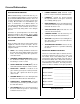
General Information HIGHLIGHTED INFORMATION Walker Manufacturing recommends that any service requiring special training or tools be performed by an authorized Walker Mower Dealer. There are several general practices to be aware of in the area of safety. Most accidents associated with the operation or maintenance of a Walker Mower are caused by disregarding basic safety precautions or specific warnings. Such accidents, in most cases, can be prevented by being aware of the dangers present.
General Information Serial Number Tractor Serial Number Location SERVICING OF ENGINE AND DRIVETRAIN COMPONENTS The detailed servicing and repair of the engine, hydrostatic transmission, and gearboxes are not covered in this manual. Only routine maintenance and general service instructions are provided. For the service of these components during the limited warranty period, it is important to find a local, authorized servicing agent of the component manufacturer.
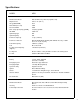
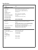
Specifications MODEL MDD ENGINE Manufacturer/Model Kubota D722, 3 Cyl., Diesel (Liquid Cooled) Displacement 44.0 cu. in. (722 cc) HP (@ 3600 RPM) 20.9 Max. RPM (No Load) 3800 Governed RPM 3600 Max. Torque [ft-lb (N·m) @ RPM] 34 (46.1) @ 2600 Idle RPM 1000 ± 50 Spark Plug Type N/A Spark Plug Gap N/A Crankcase Capacity 3.1 qts (2.
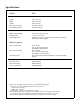
Specifications MODEL MDD TRANSMISSION (continued) Service Brake Dynamic Braking through Hydrostatic Transmission Parking Brake Mechanical Pin Lock in Transmission Gear Neutral Transmission Release by Manual Dump Valve Final Drive Transmission Fluid Gear Drive Axle Factory Service Mobil 1 Synthetic Motor Oil (15W50) Alternate Transmission Fluid SAE 30W Straight Viscosity Motor Oil Transmission Fluid Capacity 1 qt (1 liter) Transmission Cooling Ground Travel Speed Cooling Fan Mounted on Drive
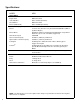
Specifications MODEL MDD DIMENSIONS (Tractor and Mower)* Length 91 in. (231 cm) Width 49 in. (124 cm) Height 44 in. (112 cm) Wheel Base (Tractor) 42-1/4 in. (107 cm) Tread Width (Tractor) 29-3/4 in. (76 cm) MOWER DECK Width of Cut SD/GHS 42 or 48 in. (107 or 122 cm) Cutting Height 1 to 4 in. (3 to 10 cm) Height Adjustment 7 Positions - 1/2 in. (1 cm) Increment Hitch Pins Installed in Multi-Position Deck Support Blade Size (Typical) 42 in. (107 cm) SD 22 in. (56 cm) 2 in.
Specifications MODEL MDD DRIVE BELTS Engine PTO Walker P/N 7230 Jackshaft Drive Gates 3VX335 (P/N 6231) Ground Drive Walker P/N 7248 Blower (GHS Model) Gates 3VX280 (P/N 7234-1) GHS SYSTEM (Optional) Blower 4 x 10 x 1/4 in. (10 x 25 x 1 cm) Three-Blade Paddle Wheel (Driven by Mower Engine) Blower Brake Band Brake (Works in Combination with PTO Clutch, Stops Blower within Five (5) Seconds of PTO Disengagement) Max. Blower Speed 3600 RPM Grass Catcher Capacity 65 Gallons (246 liters)/7.
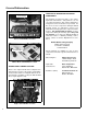
Component Identification NOTE: Control Identification shown in Operating Instructions section. Catcher Door Safety Latch Turbine Precleaner Grass Handling System 9.
Component Identification Catcher Door Gas Spring Protective Cover Removable Grass Catcher Screen (Not Visible) Catcher Door Gas Spring Catcher Exhaust Deflector Radiator Cap Radiator Catcher Lift / Dump Handle Instrument Panel Guard Catcher Door Instrument Panel Box (Shock Mounted) Catcher Door Handle Dump Plate Left Hand Drive Wheel Radiator Guard Muffler and Tailpipe Radiator Screen Rear View and Left Side View 8 Anti-Scuff Roller Fuel Filter Coolant Recovery Tank Tailwheel Fork and Wheel
Component Identification Muffler Air Cleaner Cover Donaldson Air Cleaner Tailpipe Overflow Hose Radiator Cap Air Restriction Indicator (Not Visible) Radiator Precleaner Tube Radiator Guard Jackshaft PTO Gearbox Dipstick GHS Blower Turbine Precleaner RH Transmission Lockout Lever RH Hydrostatic Transmission 40 Amp Circuit Breaker PTO Clutch Lever Neutral Safety Switch LH Transmission Lockout Lever 30 Amp Circuit Breaker Positive (+) Battery Cable Negative (-) Battery Cable Battery LH Hydrost
Component Identification Starter Motor Below (Not Visible) Exhaust Manifold Water Temperature Gauge Sender Oil Fill Cap Alternator Thermostat Housing and Thermostat Glow Plug(s) Water Pump Fuel Pickup Line Fuel Return Line Fan Motor Fuel Tank Cap Radiator Screen (Removable) Radiator Fan and Shield Air Intake Hose Injectors Injection Pump Throttle Control Linkage Lever Top View (Engine Compartment) 10 Engine Stop Lever Linkage (Fuel Shut-Off Valve)
Safety Instructions Pay particular attention to any information labeled DANGER, WARNING, CAUTION, IMPORTANT, and NOTE in this manual. When you see the Safety Alert Symbol ( ), read, understand, and follow the instructions. Failure to comply with safety instructions may result in personal injury.
Safety Instructions 6. 7. 8. 9. Do not wear loose fitting clothing that could get caught in moving parts. Do not operate this machine while wearing shorts; always wear adequate protective clothing, including long pants. Wearing safety glasses, safety shoes, and a helmet is advisable and required by some local ordinances and insurance regulations. Prolonged exposure to loud noise can cause impairment or loss of hearing.
Safety Instructions 9. Watch for holes, rocks, and roots in the terrain and for other hidden hazards. When mowing tall grass, mow higher than desired to expose any hidden obstacles. Then, clean the area and mow to the desired height. 10. Avoid sudden starts or stops. Before backing the machine up, look to the rear to be sure no one is behind the machine. Watch carefully for traffic when crossing or working near roadways. 11.
Safety Instructions MAINTENANCE 1. 2. 3. 4. 5. 6. To prevent accidental starting of the engine when servicing or adjusting the machine, remove the key from the ignition switch and disconnect the electrical plug on the fuel shut-off solenoid. To reduce fire hazards, keep the engine free of grass, leaves, excessive grease, and dirt. Keep all nuts, bolts, and screws tight to ensure the machine is in a safe, working condition. Check the blade mounting nuts frequently, making sure they are tight.
Safety Instructions SAFETY, CONTROL, AND INSTRUCTION DECALS Safety, Control, and Instruction Decals are installed on the machine; if any are missing, illegible, or damaged, a replacement should be ordered and installed before putting the machine into operation. The Decal Part Number is listed below and in the Parts Manual.
Safety Instructions SAFETY, CONTROL, AND INSTRUCTION DECALS Safety, Control, and Instruction Decals are installed on the machine; if any are missing, illegible, or damaged, a replacement should be ordered and installed before putting the machine into operation. The Decal Part Number is listed below and in the Parts Manual.
Assembly Instructions SETUP INSTRUCTIONS Dry Battery Service Walker Mowers are shipped partially assembled. After uncrating the tractor and mower deck, initial setup is required. DANGER Activating a battery can be dangerous. The battery should be taken to a reliable service station, battery store, or power equipment dealer where a trained technician can activate the battery safely. DO NOT attempt to activate the battery unless you are experienced in battery service work.
Assembly Instructions Battery Charging WARNING DANGER Make sure the battery cap vents are open. Improper venting of the battery COULD cause a battery explosion. BATTERIES PRODUCE EXPLOSIVE GASES • Charge the battery in a well-ventilated area, so that gases produced while charging can dissipate. • Keep sparks, flames, and smoking materials away from the battery at all times. • Make sure the battery cap vents are open after the battery is filled with acid (check manifold vent on each cap).
Assembly Instructions Deck Discharge Shield Installation (Side Discharge Models Only) Grease Fitting Locations Attach the deck side discharge shield by positioning the shield hinge lug in front of the deck mount and fastening with two 3/8-16 x 1-1/4 in. bolts, 3/8-16 ESNA nuts, and 3/8 in. wave spring washers. The wave washers fit between the two hinging surfaces. Tighten the nuts until the shield moves freely but is not loose.
Assembly Instructions 5. Attach Spring Roller Wheels Tilt-Up Spring and Roller Wheel Installation on Rear Discharge Deck Mower Deck lnstallation on Tractor Deck Installation 1. Lightly grease each deck support arm (2) on the tractor. Refer to Mower Deck Installation photo on next page for location of deck support arm. 2. Engage the deck carrier frame tube sockets on the tractor support arms (refer to Discharge Chute and PTO Shaft Guard Installation photo for socket location).
Assembly Instructions 6. Raise the front mower body (instead of lifting the front of deck) and clip the counterweight springs to the receptacle on front of body. Lower the front body to tension the springs. (Refer to Deck Counterweight Spring Installation photo.) Grease Deck Support Arms PTO Connection Arrows on Shaft and Tube (used to align when sliding together) Mower Deck Installation (PTO Shaft Connection) 7.
Assembly Instructions Deck Leveling 1. 2. Check the side-to-side level. Rotate each blade sideways and measure the distance from blade tip to ground on each side. If measurements vary more than 1/8 in. (3 mm), add a washer shim under the deck support pins on the low side to level the deck. 3. Check the front-to-rear level. Rotate the blades to point forward. Measure the distance from blade tip to ground on the front and rear. The rear of the blade should be 1/8 to 1/4 in.
Assembly Instructions PREOPERATING CHECKLIST Before operating the mower for the first time, and as a routine before daily operations, it is important to make sure the mower is properly prepared and ready for operation. The following is a list of items to be checked. (For a mower with frequent operation, some of these items will not need to be checked every day, but the operator should be aware of the condition of each.) For proper fuels and lubricants refer to Specifications.
Assembly Instructions CHECK HYDROSTATIC TRANSMISSION OIL LEVEL Refer to LUBRICATION for Checking Hydrostatic Transmission Fluid Level in Maintenance Instructions. Tilt-Up Lift Handle Tilt-Up Latch Tilt-Up Latch CHECK BATTERY ELECTROLYTE LEVEL Refer to CHECKING/SERVICING the Battery in Maintenance Instructions. CHECK FUNCTIONS OF INSTRUMENT PANEL AND WARNING HORN Turn the ignition key to the RUN position.
Operating Instructions CONTROL IDENTIFICATION, LOCATION, AND FUNCTION Operating Controls CAUTION Engine Throttle The throttle control lever (red knob) is located on the left side of the seat and is used to control engine speed. Moving the lever forward toward the FAST position increases engine speed; moving it backward toward the IDLE position decreases engine speed. Before operating the mower, become familiar with the location and function of all operator controls.
Operating Instructions Forward Speed Control (FSC) Parking Brake Forward Speed Control (FSC) has two functions: One is to set forward travel speed, and the other is to establish the NEUTRAL-PARK position. When the FSC lever is moved into the FORWARD position, a friction lock holds any forward speed setting from 0 to 5 mph (0 to 8 km/h). The ground speed is proportional to the lever position; the further the lever is advanced forward, the faster the tractor moves.
Operating Instructions Transmission Lockout Levers Cold Start Lever (Jackshaft Drive Belt Release) The transmission lockout levers disengage the hydrostatic transmissons. By lifting the lever on top of the transmission and locking it into place with the lockout cam, the hydrostatic transmissions are released to permit freewheeling. By releasing the cam and lowering the lever, the transmissions are engaged for normal operation.
Operating Instructions The Forward Speed Control also Establishes the Neutral-Park Position of the Steering Levers LEFT WHEEL STEERING LEVER RIGHT WHEEL STEERING LEVER FORWARD SPEED CONTROL LEVER (FSC) Full Forward Ground Speed Position Forward Position (No Control Change) Intermediate Ground Speed Position Neutral-Park Position Neutral-Park Position Reverse Drive Wheel Motion Position PARKING BRAKE Engaged Position Disengaged Position Disengaged Position THROTTLE Fast Throttle Position Idle Posi
Operating Instructions Instrument Panel This illustration shows the configuration of the switches and indicators located on the instrument panel.
Operating Instructions • Engine fan belt Voltmeter The voltmeter displays battery and charging system voltage. An indication of low or high voltage (the red area) indicates an electrical system failure. The cause of the failure should be determined and corrected. Water Temperature Gauge The water temperature gauge monitors engine cooling system temperature.
Operating Instructions Light Switch (For Optional Lights) 1. Operates headlights (when installed). Hourmeter Before attempting to start the engine, make sure the operator is in the seat, the Forward Speed Control is in NEUTRAL-PARK position, and the blade clutch and parking brake are DISENGAGED. NOTE: Release parking brake to prevent extra load on the starter if the transmission neutral is slightly out of adjustment.
Operating Instructions 3. Move the throttle 1/4 to 1/2 open (toward FAST) and turn the ignition switch to the START position to start the engine. Release the key to the RUN position as soon as the engine starts. IMPORTANT: If the engine fails to start after approximately 10 seconds of cranking, the engine should be checked before further cranking. Turn the key to the OFF position and allow a 60 second cool-down period between starting attempts.
Operating Instructions NOTE: If the FSC lever will not stay in the selected position, the friction lock needs to be adjusted. Refer to ADJUSTMENTS of Forward Speed Control Friction Lock in Maintenance Instructions. ADJUSTING GROUND SPEED AND STEERING IMPORTANT: If the DSD52 or DSD62 Mower deck is installed on the tractor, make sure the dolly wheel is retracted BEFORE moving. CAUTION Learn to START, STOP, and MANEUVER the mower in a large, open area.
Operating Instructions ENGAGING THE MOWER Pull Steering Levers With Left Hand 1. Set the engine throttle at about 1/3 speed. Do not attempt to engage the blade clutch at high engine speeds. This will drastically shorten drive belt life. Use only moderate engine speed when engaging the blade clutch. 2. Pull the blade clutch lever SLOWLY up to engage the mower blades. CAUTION Forward Speed Control Keep Feet On Footrest (FSC) When Moving Correct Operator Hand Position on the Controls 3.
Operating Instructions IMPORTANT: DO NOT disengage the blade clutch with high engine speed (above 1/2 throttle) since the brake action on the blade drive will cause premature wear of the brake band. WARNING A brake stops the cutter blades (and blower on GHS equipped models) from freewheeling within five (5) seconds after disengaging the clutch. If the brake system malfunctions and the blades do not stop within five (5) seconds, the brake should be adjusted or repaired before operating the mower.
Operating Instructions Cutting height is adjusted by positioning the four retainer hitch pins in a series of seven vertical holes on the deck support pins. Lift handles have been provided on each end of the deck to assist in raising the deck while positioning the hitch pins. Cutting heights range from 1 in. (25 mm) [top holes] to 4 in. (102 mm) [bottom holes] in 1/2 in. (13 mm) increments.
Operating Instructions RECOMMENDATIONS FOR MOWING IMPORTANT: Operate the engine at full speed when mowing, to allow the engine to produce full horsepower and to increase efficiency of the engine cooling system. • Keep the mower deck and discharge chute clean. • Mow with sharp blades. A dull blade tears the • When using a side discharge mower deck, the side discharge shield must not be removed and must be kept in the lowest possible position to deflect grass clippings and thrown objects downward.
Operating Instructions RECOMMENDATIONS FOR TILT-UP DECK OPERATION/TRANSPORT To avoid potential deck and/or tractor damage while using the tilt-up deck, the following recommendations are offered: • Do not move the tractor with the deck in the tiltup position since both the roller wheels (on the back of the deck) and the GHS discharge chute may be damaged by moving the tractor. The tilt-up configuration should only be used when the tractor is parked.
Operating Instructions GRASS HANDLING SYSTEM (GHS) GHS Model Only Exhaust Screen (Removable) Catcher Door Safety Latch Grass-Pak® Vane Switch Powerfil ® Drive Motor Exhaust Deflector Actuator Rod “Full” Signal Horn PTO Clutch Delivery Chute Catcher Door Catcher Door Spring PTO and Blade Gear Drive Grass Catcher Dump Handle Powerfil ® Delivery Spout Body Chute Assembly Blower Deck Discharge Chute Rear Discharge Mower Deck GHS Flow and Components 39
Operating Instructions General Information The Grass Handling System (GHS) consists of a rear discharge mower deck connected to a 10 in. (25 cm) blower and a rear mounted grass catcher with 7.0 bushel (246 liters) capacity or optional 9.5 bushel (335 liters) capacity. The GHS blower operates any time the mower blade clutch is engaged and moves grass through the rear discharge deck chute into the grass catcher. Blower airflow is exhausted out the back of the grass catcher, through a filtering screen.
Operating Instructions Clogging Checklist • Check the amount of flat section remaining at In case of clogging, there will be a distinct change in the sound of the blower, i.e., the blower sound will stop. Also, the mower deck will begin to leave a trail of grass clippings. When this occurs, stop the engine, disconnect the electrical plug on the fuel shut-off solenoid, and make sure all movement has stopped before attempting to unclog. blade tip.
Operating Instructions • Check that the openings in the removable air exhaust screen in the grass catcher are not plugged. If the screen is clogged, refer to Cleaning the GHS Exhaust Screen in this section. Remember, anything that restricts airflow or material flow along the entire path from the mower deck to the grass catcher can cause clogging. Using the Tilt-Up Deck Refer to CLEANING of Grass Buildup in Mower Housing in Maintenance Instructions.
Operating Instructions Grass Catcher Screen Safety Latch Removal Knobs (Not Visible) Catcher Door Safety Latch Grass Catcher Screen Removal for Cleaning Using the Dump Bag Dumping the Catcher 1. For dumping, the catcher either tailgate dumps into a disposal area or dumps into the optional dump bag. The dump bag is a reusable nylon fabric bag designed to conveniently move grass clippings from the catcher to a remote disposal area or container. Tailgate Dumping 1.
Operating Instructions 3. Hook the bottom of the bag over the rear bumper while lifting on the handle strap. 4. Tilt the catcher back to dump into the bag by lifting on the catcher lift handle on the lower front corner of the catcher with the one hand while continuing to hold up on the bag strap with the other hand. Refer to photos for positioning the bag and dumping. Power Dump Option When equipped with the optional power dump system, the operator dumps the catcher while sitting in the seat.
Operating Instructions Door Actuator Arm Grass Catcher Catcher Door Gas Spring Cable Guide Lift Channel Rear Body Panel, RH Power Dump Ram Actuator Fork Catcher Door Cable Rod Guide Cable Assembly Rear Body Panel, LH Gas Spring Actuator Mount Assembly Dog Leg Assembly Rubber Bumper Power Dump Components 45
Maintenance Instructions CAUTION Maintenance procedures requiring special training or tools should be performed by a trained technician.
Maintenance Instructions IMPORTANT TIPS FOR CARE OF THE KUBOTA ENGINE Fuel System KUBOTA TIPS • Maintain proper fluid levels in the radiator and overflow tank. • Operate the engine at full speed when mowing. • Fuel must be clean - free from water, dirt, and or- This will allow the engine to produce full horsepower and move more cooling air through the radiator. ganic material. Fuel contamination will greatly shorten the life of the fuel injection pump and injectors.
Maintenance Instructions LUBRICATION LUBRICATION IMPORTANT: DO NOT operate engine without a sufficient oil supply in the crankcase. DO NOT operate with the oil level below the lower mark or above the upper mark on the dipstick. WARNING DO NOT attempt to lubricate the machine with the engine running. Disengage the PTO clutch, shut off the machine, and remove the ignition key. 5. If additional oil is needed, refer to Specifications for proper crankcase lubricant.
Maintenance Instructions Drain Plug Oil Drain Location (view from left side of tractor) 4. Before removing the oil filter, clean the area around the filter to keep dirt and debris out of the engine. Oil Filter LUBRICATION 7. Install the new oil filter on the engine. Turn the filter clockwise until the rubber gasket contacts the sealing surface, then tighten the filter an additional 1/2 turn. 8. Reinstall the drain plug. Make sure it is tightened to 10 ft-lb (13.6 N·m). 9.
Maintenance Instructions Ident No.
Maintenance Instructions 1 2 LUBRICATION 3 2 1 4 4 5 6 7 8 7 9 7 8 7 40 10 13 9 11 14 14 39 12 15 16 15 17 18 16 21 37 19 20 28 & 38 21 34 33 23 22 37 36 35 26 27 34 24 28 33 25 29 30 30 31 32 31 Chassis and Deck Lubrication Points 51
Maintenance Instructions LUBRICATION NOTE: In case the gearboxes are completely drained of oil, approximately 5 fl. oz. (15 cl) of oil per gearbox is required to refill the gear drive assembly. Mower Deck Gearbox Lubrication NOTE: These instructions apply to all mower decks with gear-driven blades. Refer to DSD52 or DSD62 Mower Deck Lubrication in this section for the DSD52 or DSD62 deck with belt-driven blades.
Maintenance Instructions 2. LUBRICATION Check the oil level in the belt drive gearbox every 100 hours (or sooner if a visible oil leak has developed). With the deck in the normal operating position, remove the level plug in the side of the gearcase. Add SAE E.P. (Extreme Pressure) 90W oil to maintain the oil level to the plug. If the oil level is low, check the gearbox for any indication of an oil leak. If an oil leak is noted, the gearbox will need to be removed and rebuilt. 3.
Maintenance Instructions LUBRICATION Hydrostatic Transmission Fluid b. If no fluid leaks from around the air bleed plug: Checking Hydrostatic Transmission Fluid Level * Slowly add fluid into the reservoir until fluid starts to leak from around the plug. (Transmissions are serviced from the factory with Mobil 1 (15W50) Synthetic Oil). When it is necessary to add fluid, refer to Specifications for the proper fluid.
Maintenance Instructions LUBRICATION/CLEANING 3. Reinstall the lower drain plug, making sure the rubber O-ring on the plug is in place and in good condition. 6. Before installing the air bleed plug, fill the reservoir with fluid allowing a small amount to leak out of the air bleed plug hole. 4. Refill the transmission through the air bleed plug hole until it is as full as possible. 7. Install the air bleed plug and fill the reservoir to the COLD level line.
Maintenance Instructions CLEANING Turbine Precleaner The turbine precleaner is mounted on a remote air intake tube connected to the Donaldson air cleaner. A spinning fan driven by the intake airflow separates dust from the air, giving the initial stage of air cleaning. Dust particles are exhausted through a single small vent in the side of the housing. Since no dust is trapped, the precleaner operates without cleaning.
Maintenance Instructions 1. 2. 3. Release the top and bottom cover latches and remove the air cleaner cover. Wash the cover and Vacuator™ valve. Check that these components are in good condition. The Vacuator™ valve is subject to wear and deterioration and should be replaced yearly or when damaged. The lips of the valve should close and fit together; any cracks, deformation, or wear in the valve is cause for replacement. CLEANING 8.
Maintenance Instructions 10. Check the air intake hose for cuts, nicks, etc., and the hose clamps for tightness. 11. Reset the air restriction indicator (press button on bottom). CLEANING Flushing Radiator and Changing Coolant Change engine coolant every year. Drain the coolant from the engine and radiator: 1. Remove the radiator cap. 2. Open the drain cocks on the engine block and radiator (see the Kubota Owner's Manual for location of the drain cocks). Also, drain the coolant recovery tank. 3.
Maintenance Instructions CLEANING GHS Blower Tilt-Up Lift Handle Tilt-Up Latch Tilt-Up Latch Tilt-Up Hook on Deck Normally, the GHS blower operates with no maintenance or cleaning. However, when mowing grass that is dirty and damp (especially springtime mowing), a deposit of dirt may accumulate inside the blower housing, causing wear and binding of the blower wheel. When operating in these conditions, inspect the blower frequently for dirt buildup.
CLEANING/ CHECKING/SERVICING Maintenance Instructions 3. Reinstall the GHS blower drive belt by reversing the removal procedure. An additional procedure in maintaining transmission cooling is to inspect the cooling fans. Replace the fan(s) if blades are missing or damaged.
Maintenance Instructions Check the coolant level in the coolant recovery tank and maintain the coolant level between the FULL and LOW marks on the recovery tank. When the engine is cold, the coolant level should be at or slightly above the LOW mark on the recovery tank. If the coolant level is low, remove the radiator cap and fill to the overflow port level and then fill the recovery tank above the LOW mark.
Maintenance Instructions CHECKING/SERVICING Charging the Battery NOTE: Keep blades sharp - cutting with dull blades not only yields a poor mowing job but slows the cutting speed of the mower and causes extra wear on the engine and blade drive by pulling hard. Check the battery charge by measuring the specific gravity of electrolyte; if specific gravity is less than 1.225, the battery will need to be charged as follows: 1. Charge the battery at 15 amps for 10 minutes.
Maintenance Instructions CHECKING/SERVICING NOTE: Blades can be sharpened with an electric blade sharpener, conventional electric grinder, or a hand file. CAUTION ALWAYS wear eye protection and gloves when sharpening a blade. Sharpen at Original 30° Angle Intersection Wear Area 7. Mount the blade with wing tips pointing up into the housing. Reinstall the blade, washer, lock washer, and nut. Tighten the nut to 60 ft-lb (81.3 N·m).
Maintenance Instructions Fuel Lines and Clamps Every year, inspect the fuel supply line from the tank to engine for deterioration or damage. Also, inspect the fuel line clamps for tightness. Good preventive maintenance calls for complete replacement of fuel lines and clamps every two (2) years. NOTE: This procedure is of special importance for the diesel engine due to poor performance when air is injected with the fuel.
CHECKING/SERVICING/ REPLACING/REPAIRING Maintenance Instructions Fuel Control Arm In Open (Run) Position Fuel Shut-Off Valve Throttle Control Arm (Noted For Reference) Fuel Valve Open (Engine START and RUN Position) If the fuel valve solenoid is not operating properly, the problem may be isolated by first checking the operation of the solenoid as follows: 1. Disconnect the fuel valve solenoid wire plug from the wire harness. 2. Make jumper wire connections from the solenoid to the battery: a.
Maintenance Instructions Jackshaft Drive Belt REPLACING/REPAIRING Engine PTO Belt Engine Fan Belt Hydrostatic Ground Drive Belt GHS Blower Belt (GHS Model Only) Belt Locations 66
Maintenance Instructions REPLACING/REPAIRING Engine PTO Drive Belt (3 Groove Power Band) 1. c. To remove the engine PTO drive belt: a. Remove the jackshaft drive belt from its idler pulley (by pushing down on cold start lever) and let the belt drop down out of the way. 2. Remove the PTO drive belt by “walking” the belt off of the engine and PTO pulleys one groove at a time until the belt is completely removed. Install the PTO drive belt by reversing the removal procedure.
Maintenance Instructions REPLACING/REPAIRING Jackshaft Drive Belt 1. b. Slide the idler arm release down to unlock the idler arm from the spring lever. Then pivot the arm up and away from the belt. c. Roll the belt off the jackshaft pulley and remove. To remove the jackshaft drive belt: a. Relax the belt by releasing spring tension from the jackshaft drive idler arm using the cold start lever.
Maintenance Instructions REPLACING/REPAIRING GHS Blower Drive Belt 1. Remove the GHS blower drive belt tension by depressing the idler pulley on the tightener arm. Roll the belt off the blower pulley. The belt should be clear of the blower pulley, allowing free movement of the blower wheel. Blower Drive Pulley Blower Pulley GHS Blower Drive Belt Belt Tightener Idler Pulley (Disengaged) GHS Blower Drive Belt Assembly (Disengaged) Blower Drive Belt Spring Removal 2.
Maintenance Instructions REPLACING/REPAIRING Hydrostatic Ground Drive Belt 1. To remove the hydrostatic ground drive belt: a. b. Slide belt off pulleys, then release the idler. Raise the spring-loaded belt tightener arm and idler pulley to relax belt. Belt Tightener Arm Jackshaft Spring Transmission Drive Pulley Idler Pulley Hydrostatic Ground Drive Belt Hydrostatic Ground Drive Belt Assembly (Disengaged) 2. Reverse the procedure to install the hydrostatic ground drive belt.
Maintenance Instructions REPLACING/REPAIRING Engine Fan Belt 1. b. To remove the fan belt: a. Pivot the alternator as shown to relax and remove belt. Loosen the alternator mounting pivot bolt and the alternator bracket tensioner bolt. Alternator Bracket Tensioner Bolt Engine Fan Belt Alternator Water Pump Pulley Crankshaft Pulley Engine Fan Belt (Loose) 2. Reverse the procedure to install the belt.
Maintenance Instructions REPLACING/REPAIRING Fuel Filter Blade Overload Shear Bolts Model MDD has two (2) fuel filters. Replace both the in-line filter and the Kubota filter element every 400 hours of operation. NOTE: Shear bolts are not used on the DSD62 mower deck. Kubota Fuel Filter In-Line Filter Cold Start Lever (For Reference) The cutting blade is keyed to the blade hub by two (2) shear bolts (10-24 x 5/8 in. stainless steel machine screws).
Maintenance Instructions REPLACING/REPAIRING PTO Shear Pin Mower Blades The PTO drive shaft connection to the deck gearbox has a shear pin to provide shock load protection to the mower deck drive. This system provides primary shock protection in case of blade impact and will normally shear before the individual shear bolts on the blade hub. Mower blades are removed and remounted as described in Sharpen Mower Blades instructions (refer to CHECKING/SERVICING in this section).
Maintenance Instructions Reinstall the blades following procedure from Sharpen Mower Blades instructions in CHECKING/ SERVICING in this section. If blades are replaced, always use Walker original equipment blades to ensure safety and optimum performance. The quality and performance of replacement blades offered by other manufacturers cannot be guaranteed, they could be dangerous. REPLACING/REPAIRING 6.
Maintenance Instructions REPLACING/REPAIRING GHS Blower Assembly (and/or Blower Wheel) Blower Wheel Removal GHS Blower Assembly Removal When required, replace the blower wheel using the following procedure: 1. Remove the mower deck. Refer to Deck Installation in Assembly Instructions and reverse the procedure to remove the deck. Skid Bar Mounting Bolts Blower Assembly Skid Bar Remove Skid Bar for GHS Blower Removal 2. Remove the blower faceplate by removing six (6) 1/4-20 nuts. 3.
REPLACING/REPAIRING Maintenance Instructions Blower Wheel Installation GHS Blower Assembly Installation 1. To install the blower wheel, reverse the removal procedures. The front bearing is mounted on the blower wheel shaft, secured by a locking collar. Drive the locking collar clockwise with a punch, and tighten the set screw. Reinstall the blower assembly into the mower using the reverse procedures of GHS Blower Assembly Removal. 2. Press blower wheel and front bearing into the blower housing.
REPLACING/REPAIRING/ ADJUSTMENTS Maintenance Instructions 4. 5. 6. Reinstall the solenoid. At this point, move the solenoid linkage by hand and check for any binding or dragging of the solenoid plunger and linkage. If the solenoid does not move freely, adjust the solenoid mounting position by bending the mount and/or loosening the mounting bolts. The solenoid must move freely for proper operation.
Maintenance Instructions ADJUSTMENTS Blade Clutch (PTO) Clutch Disengagement/Brake Action PTO Drive Pulley Engine Pulley WARNING It is important to check and maintain blade brake action for safe operation of the machine. The declutched or disengaged position of the blade clutch idler pulley is adjustable and is set to give belt release without excessive slack and to apply the blade brake. The blade brake is activated by linkage to the clutch idler pulley mechanism.
Maintenance Instructions ADJUSTMENTS Transmission Control 2-1/8 in. (54 mm) IMPORTANT: The proper adjustment of the transmission control stops is essential for efficient operation and life of the transmission. These stops are properly adjusted at the factory and should only require readjustment if the transmission or related control linkage is removed or changed.
Maintenance Instructions Steering Lever End Play Adjustment - Step 2 1. Position the FSC lever to the most FORWARD position. 2. Loosen the adjustment nut on each steering lever actuator until end play develops between the lever actuator and the adjustment nut (sliding on transmission control rod). 3. Hold the actuator back as shown (against the spring pressure) and tighten the nut to the point where the end play is removed and then tighten two additional turns.
Maintenance Instructions ADJUSTMENTS 2. With the steering levers held back, move the FSC lever back from the FORWARD position. With a proper amount of friction adjusted, the FSC lever should move back with a slight amount of resistance (friction). If the FSC lever movement is “stiff”, the friction needs to be decreased. 3. The FSC friction is increased or decreased by tightening or loosening the friction adjustment nut.
Maintenance Instructions ADJUSTMENTS IMPORTANT: The solenoid linkage should be checked and adjusted any time the solenoid is removed and replaced (either reinstalling an existing solenoid or installing a new replacement). b. Turn the ignition switch ON and move the blade clutch to the ENGAGED position (engine not running) to make the horn sound. Check and adjust the solenoid linkage as follows: c. If the horn does not sound, the horn is bad and needs to be replaced. d.
Maintenance Instructions ELECTRICAL SYSTEM For troubleshooting, refer to Wiring Diagram. ELECTRICAL SYSTEM IMPORTANT: Disconnect both battery cables before unplugging any wiring connectors or making repairs on the electrical system. IMPORTANT: Disconnect the battery cables before unplugging and removing the instrument panel.
Maintenance Instructions ELECTRICAL SYSTEM WALKER MODEL MDD Beginning S/N 2001-49370 IGNITION SWITCH CIRCUITS OFF ALL OPEN 30 + 19 + AC GLOW PLUG START 30 + 17 + 50 + AC RUN 30 + AC Wiring Diagram - Model MDD FUEL PUMP GRASS PAK SWITCH BLK BLK/WHT BLK/WHT RED BLK/WHT YEL POWERFIL R MOTOR BLK/WHT 30 = BATTERY 17 = START / REVERSING MODULE 19 = GLOW PLUGS 50 = START AC = FUEL PUMP, FUEL SOLENOID GAUGES, AND FAN R BLK BLK RELAY - A FUEL SOLENOID START RELAY (PULL) OFF 30 + 87A GLOW PLUG 30 + 87 30
0$,17(1$1&( $1' 6(59,&( 5(&25' 6+((7 '$7( 6(59,&( ,7(0 (1*,1( +2856 BBBBBBBBBBBBBBBBBBBBBBBBBBBBBBBBBBBBBBBBBBBBBBBBBBBBBBBBBBBBBBBBBBBBBBBBBBBBBBBBBBBBBBBBBBBBBBBBBBBBBBBBBBBBBB BBBBBBBBBBBBBBBBBBBBBBBBBBBBBBBBBBBBBBBBBBBBBBBBBBBBBBBBBBBBBBBBBBBBBBBBBBBBBBBBBBBBBBBBBBBBBBBBBBBBBBBBBBBBBB BBBBBBBBBBBBBBBBBBBBBBBBBBBBBBBBBBBBBBBBBBBBBBBBBBBBBBBBBBBBBBBBBBBBBBBBBBBBBBBBBBBBBBBBBBBBBBBBBBBBBBBBBBBBBB BBBBBBBBBBBBBBBBBBBBBBBBBBBBBBBBBBBBBBBBBBBBBBBBBBBBBBBBBBBBBBBBBBBBBBBBBBBBBBBBBBBBBBBBBBBBBBBBBBBBBBBBBBBB
Operator’s Notes 86
LIMITED WARRANTY FOR WALKER COMMERCIAL RIDER MOWER 1. WHAT THIS WARRANTY COVERS, AND FOR HOW LONG: Walker Manufacturing company will, at its option, repair or replace, without charge, any part covered by this warranty which is found to be defective in material and/or workmanship within one (1) year* after date of sale to the original retail purchaser unless the product is used for rental purposes, in which case this warranty is limited to ninety (90) days.
Lwa 105 LpA 93 OPERATOR Sound - Model MDD Vibration - Model MDD Sound Test Vibration Level Sound test conducted was in accordance with 79/113/EEC and was performed on 28 January 98 under the conditions listed: General Condition: Cloudy Temperature: 32 (F)o 0 (C)o Wind Speed: < 5 mph (< 8 kmh) Humidity: 58% 0.8g Vibration levels at the operators handles were measured in the vertical, lateral, and longitudinal directions using calibrated vibration test equipment.