ENERGY MANAGEMENT SOLUTIONS Power Boost and Eco-Smart Installation Guide Version 1.
Index 2 Purpose and Scope of the Document 4 Getting Started 6 Power Meter Installation 10 Configuration 44 Power Boost 44 Eco-Smart 52
POWER METER INSTALLATION Purpose and Scope of the Document The purpose and scope of the document is to outline the instructions for the installation of the Eco-Smart and Power Boost Energy Management Solutions.
POWER METER INSTALLATION Getting Started Important Notes A. Install the charger following the instructions listed in B. C. D. E. F. the chargers’ Installation Guide. Refer to the user guide on the Wallbox Academy page for more information. Only use smart meters sold by Wallbox or a Wallbox certified reseller approved for use with Wallbox Energy Management Solutions. Installations should be performed only by qualified personnel in accordance with applicable local regulations.
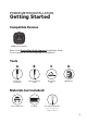
POWER METER INSTALLATION Getting Started Compatible Devices Wallbox Pulsar Plus Refer to the Pulsar Plus North America Installation Guide for a complete list of tools required for installation.
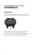
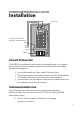
POWER METER INSTALLATION Installation Preparation Use the small opening located at the bottom of the charger between the power input and the EV connector cable output. When using this opening for the communications cabling, first remove the screw plug. Use a wrench to hold the interior lock nut while unscrewing the plug using a flathead screwdriver from the bottom (exterior) side of the plug.
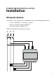
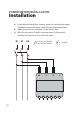
POWER METER INSTALLATION Installation Wiring the System This meter is only supported on installations with the following requirements: • 3 wire installation: 2 hot wires + neutral • Phase to phase voltage: 208-240 V • Phase to neutral voltage: 120 V Follow the diagram for wiring the system: N L1 L2 N 13 1 14 15 16 3 2 17 18 7
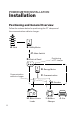
POWER METER INSTALLATION Installation Positioning and General Overview Follow the scheme below for positioning the CT clamps and the communication cable to charger. A. Grid B. Utility Meter C. Main Switch D. Eletrical Panel Positioning of CT clamps E. Energy Meter Communication cable to charger F. Communication G. Breaker H. Other House Loads 8 I. Wallbox Charger J.
POWER METER INSTALLATION Installation CT clamps Connection of the meter through a devoted breaker Meter Circuit Protection The EM530 is considered a continuously connected device, so it requires an overcurrent protective device against current beyond the acceptable rating of the equipment. • • • • Use circuit breakers or fuses rated 20 Amps or less. The circuit breaker must protect L1 and L2, all the active phases. The circuit protection must comply with local standards.
POWER METER INSTALLATION Installation 2. In the electrical panel box, locate a space for mounting the meter. If possible, mount the meter inside the panel enclosure (box). 3. Add a protection for the meter in the electric box. 4. Wire the terminals N,1 and 2 from the meter to the neutral and two hot lines from your electrical panel. N L1 L2 min: 0.2 mm2/AWG24 max: 2.5mm2/AWG12 N 13 10 1 14 15 ≤ 0.
POWER METER INSTALLATION Installation 5. Connect the CT clamps to the incoming "hot" lines as shown. Important Follow the internal arrow indicating the current direction when installing the clamps.
POWER METER INSTALLATION Installation 6.
POWER METER INSTALLATION Installation 7. Connect the meter to the charger using an STP Class 5E 1600 feet/500 meter Max Length communication cable. For the communication between charger and meter only three wires are needed. The connection between terminals 7-8 is a loop for activating the end of line resistor of the communication.
POWER METER INSTALLATION Installation 8. Check that everything is connected properly in accordance with the installation manual and local regulations. 9. Proceed with the Software configuration. At this point when the meter is powered up, the screen will show a Quick Setup Menu.
POWER METER INSTALLATION Installation 9.1. Select GO. 9.2. On the Systems screen, scroll down to 2P and press Enter. 9.3. Continue to the Ct rAt Menu 9.4. Press OK. 9.5. Set the Ct rAt value up to 50, so that it matches with the 250 A clamps supplied. 9.6. The meter has been successfully configured.
POWER METER INSTALLATION Installation Disclaimer For Eco-Smart installation the following configuration must also be completed: 1. Press the ENTER button placed on the meter.
POWER METER INSTALLATION Installation 2. Press the Enter button until you reach the Settings menu.
POWER METER INSTALLATION Installation 3. Using the down arrow button, scroll to "Ct rAt Measure".
POWER METER INSTALLATION Installation 4. Press Enter. 5. Scroll down to b.
POWER METER INSTALLATION Installation 6. Press Enter. 7. Press Enter a second time to save yor settings. BACK 1 2 SAVE 3 4 5 8. Scroll down to End. 9. Scroll up to Back.
POWER METER INSTALLATION Installation Activate terminating resistance and configure current selector 1. Set the RS485 switch into position T. T NT RS4855 RS48 2. Set the rotary switch between 1 and 7, depending on the maximum current available on the connected circuit.
POWER METER INSTALLATION Installation 3. Per national and local regulations only connect your charger to a circuit with a branch circuit overcurrent protection of 125% of the selected max amperage setting of the device. As per the chart below: Position 2 3 4 5 6 7 Amps 16A 20A 24A 32A 40A 48A Circuit Breaker Rating 20A 25A 30A 40A 50A 60A For this limitation take only into account the wire and breaker installed for the EV charger.
POWER BOOST Configuration Enabling Power Boost Once you have installed your charger and the smart meter, follow these steps to enable Power Boost: 1. Make sure you have the latest version of the myWallbox app installed on your mobile device. Also make sure you have the latest software version installed on your Wallbox charger. 2. Enable Bluetooth on your mobile device and connect to 3. your charger.
POWER BOOST Configuration 4. Select the charger on which you want to enable Power Boost. 24 5. The app will synchronize with your charger. Once complete, click the icon in the top right corner of the app screen to go to Settings.
POWER BOOST Configuration 6. On the Configuration screen, select "Upgrades". 7. On the Upgrades screen, select "Power Boost".
POWER BOOST Configuration 8. Introduce the maximum current limitation of your system/electrical panel. Important Only Max Current per phase greater than 6 amps is accepted for correct performance. In case of doubt, contact Wallbox Customer Service. Disclaimer Be sure to follow all local regulations when setting up Power Boost and do not enable a higher power rating if otherwise restricted by local rules. Be sure to consult with a professional installer familiar with the regulations in your area.
ECO-SMART Configuration Enabling Eco-Smart 1. Make sure you have the latest version of the myWallbox app installed on your mobile device. Also make sure you have the latest software version installed on your Wallbox charger. 2. Enable Bluetooth on your mobile device and connect to your charger. During each of the following steps, be sure to remain within range of your Bluetooth signal (typically no more than 30 feet). 3.
ECO-SMART Configuration 4. Select the charger on which you want to enable Eco-Smart. 28 5. The app will synchronize with your charger. Once complete, click the icon in the top right corner of the app screen to go to Settings.
ECO-SMART Configuration 6. On the Configuration screen, select "Upgrades". 7. On the Upgrades screen, select "Eco-Smart". Note: It is recommended that you activate Power Boost before enabling Eco-Smart. Once you have activated Power Boost, tap the Eco-Smart icon to access its settings.
ECO-SMART Configuration 8. Tap “Let’s start” to start 9. Enable the Eco-Smart using Eco-Smart. 30 feature by switching the button to the ON position.
ECO-SMART Configuration 10. Select your preferred Eco-Smart mode: Full-Green or Eco Mode. 11. Click "Save". Eco-Smart is now active with your selected mode.
ECO-SMART Configuration Using Eco-Smart 1. 32 If necessary, unlock your charger. 2. Connect the charging cable to your EV. The LED halo will turn to light blue and the message "CONNECTED. WAITING FOR GREEN ENERGY" will display in the myWallbox app.
ECO-SMART Configuration 3. Depending on your selected mode, as the mode conditions are met, charging will start automatically after two minutes. During charging, if there is insufficient surplus green energy available for at least 30 consecutive seconds, charging will pause. Once mode conditions are met again and there is sufficient available green energy, charging will resume. Disclaimer Important • Eco-Smartmight discharge your BESS (Battery Energy System).
support.wallbox.