XBR 900-000230 Rev 0.
Revision History Dash#/Rev Date Author 0.1 04/03/2013 Eric Anderson Initial draft 0.2 04/08/2013 Eric Anderson Updated with new mechanical drawings. 0.3 04/10/2013 Eric Anderson Section 4.4 – Reduce altitude limit to 2000m. Eric Anderson Section 4.5 – Modify power supply voltage limits. Section 6 – Add power connection details. Document – Correct xConnect logo. Section 4.1 – Update unit weight. Update Power to 13W max. 0.4 04/25/2013 Description Section 1.2 – Add LPS definition. 0.
900-000230 Rev 0.
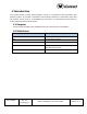
Table of Contents 1 Introduction ............................................................................................................ 5 1.1 Purpose ............................................................................................................ 5 1.2 Definitions ........................................................................................................ 5 2 Safety Warnings ......................................................................................................
1 Introduction The xConnect xBR V4 Long Range Reader is part of a proprietary data acquisition and tracking system. It provides a transmitter and multiple receivers to collect data. This data can be then sent over Wi-Fi, a wired Ethernet connection, or a fiber Ethernet connection to a data collection/concentration object. 1.1 Purpose This document provides basic installation and user instructions for the xBR V4. 1.
2 Safety Warnings 2.1 Important Safety Instructions When using this device, basic safety precautions should always be followed to reduce the risk of fire, electric shock and injury to persons. Do not use this product near water. For example, do not use: near a bath tub near a wash bowl near a kitchen sink or laundry tub in a wet basement near a swimming pool 2.
3 Regulatory Compliance 3.1 Federal Communications Commission (United States) Regulatory Compliance Information This device complies with part 15 of the FCC Rules. Operation is subject to the following two conditions: (1) This device may not cause harmful interference, and (2) this device must accept any interference received, including interference that may cause undesired operation. RF Exposure Statement The device has been found to be compliant to the requirements set forth in CFR 47 Sections 2.
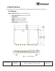
4 Specifications The xConnect xBR V4 Long Range Reader is manufactured to the following specifications: 4.1 Physical xBR V4 Assembly, PN: 300-001353 (Figure 1) Housing Material: Aluminum Alloy 6061 Dimensions: Length: 241.6mm (9.51 inches) Width: 157.5mm (6.21 inches) Height: 25.0mm (0.98 inches) Unit Weight: 910 grams (2.01 lbs.) Figure 1 – xBR v4 Module 900-000230 Rev 0.
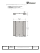
Quick Release Adapter Mount, PN: 310-006028 (Figure 2) Material: 304 Stainless Steel, Passivated Unit Weight: 297 grams (0.65 lbs.) Attaching Screw Size: M4 x 0.7 x 5mm SHCS Figure 2 - Quick Release Adapter 900-000230 Rev 0.
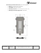
Sheet Metal Quick Release Mount, PN: 310-003470 (Figure 3) Material: 304 Stainless Steel, Passivated Unit Weight: 106 grams (0.23 lbs.) Attaching Screw Size: M5 x 0.8 x 30mm SHCS (or #10 x 1.25”) Attaching Screw Head Height Limit: 0.303 inches Figure 3 - Sheet Metal Mount 900-000230 Rev 0.
4.2 Connection Ports Ethernet 10/100 RJ-45 (POE): 100m Max. cable length Ethernet 100BASE-FX (optical) LC Connector: 300m Max. cable length, multi-mode fiber 10 SMA Antennal Ports: (1 transmit, 8 receive, 1 Wi-Fi) Circular Connector: 5 pin 4.3 RF Frequencies RX: 2401, 2424, 2450, 2474 MHz TX: 2482 MHz Wi-Fi: 802.11a/n. 5GHz only 4.
DC Pins 3,4: 14-16Vdc, 1A max (Class 2 or LPS) NOTE: If a power adapter other than one provided by the manufacturer is used in the US or Canada, it should be cULus (NRTL) Listed, with an output rated 14-16Vdc maximum, minimum 1.0A, Marked “LPS” or “Class 2”, output rated SELV, non-energy hazardous, and suitable for connection to a standard power receptacle in the US and Canada. 5 Installation 5.
- Cable runs through air between buildings are less than 42m (140ft). - Cable runs between buildings are directly buried. - Cable runs between buildings are in underground conduit, where a continuous metallic cable shield or a continuous metallic conduit containing the cable is bonded to each building grounding electrode system. *These options are from the US National Electrical Code, Sections 800.10, 800.12, 800.13, 800.31, 800.32, 800.33, and 800.40. 5.
Figure 5 - Quick Release Adapter Mount, PN-006028 The Quick Release Adaptor Mount must be securely attached to the xBR module using 4 M4x.07mm x 5mm SHCS with Loctite 220 Applied to the threads. Figure 6 - Sheet Metal Mount, PN-003470 The Sheet Metal Mount must be securely attached to the mounting surface. For example, when mounting on drywall, wall anchors, toggle bolts, or expansion anchors should be used to provide more secure attachment points. 900-000230 Rev 0.
Figure 7 - Safety Cable Attachment Point Both mounting methods provide secure mounting for the xBR. However, as an added safety feature, the xBR housing has a safety cable attachment point for overhead installations or installations where a falling device may cause a hazard (see Figure 7 Safety Cable Attachment Point). Note: This device is not to be installed in air handling spaces (i.e. not plenum rated). 900-000230 Rev 0.
6 Connection Guide The xBR V4 Long Range Reader has several connection points as shown in Figure 8 and Figure 9 - xBR V4 Connections: Figure 8 - xBR V4 RF Connections Transmit Antenna SMA – This is a female SMA connection for the transmit antenna. The transmit antenna must be installed at all times when the unit is powered up and transmitting. Transmitting without the antenna installed may damage the unit. This antenna must be of an approved or supplied type. Use of an unauthorized antenna is not allowed.
Figure 9 - xBR V4 Connections Ethernet 10/100 RJ-45 (PoE) – This is an RJ-45 jack for an Ethernet connection with optional Power over Ethernet (PoE) Ethernet 100BASE-FX – This is an LC connection for an optical Ethernet connection. DC Power Connector – This connector provides a means of powering the unit if PoE is not available. Connect only a supplied or approved power supply. The connector on the V4 is a Lemo EGG.1B.305.CYM. The mating connector is a Lemo FGG.1B.305.CLAD52Z (male pins).
When connecting a 14 to 16 Vdc power supply, use pins 4 and 5 on the connector (pin 4 positive, pin 5 negative). Leave the other pins unconnected (Figure 11). Figure 11 - DC Power Connector – 14 to 16Vdc Connection 900-000230 Rev 0.