
User's Manual


900-0153
Rev 01
xTPra & xTPrs Installation and User Guide
Page 10 of 17
Confidential and Proprietary
4.1.3 Peripheral Connector
On the xTPrs the peripheral interface connector is available. The Peripheral
Connector on the xTPra model is not connected internally.
The 18 pin Peripheral connector provides the DC input power source for the xTPrs as
well as an opto-coupled input signal.
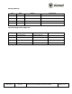
The pinout of this connector is as follows:
Pin
Function
4
+24VDC Power Input
5
+24VDC Return
10
Optically isolated input,
Current sinking or Current
Sourcing options, 24VDC
max. See “xTPrs
Configuration Options” for
more details.
1-3,6-9, 11-18
All other pins are reserved
for future use. DO NOT
CONNECT.
The part number of the peripheral connector is 14282-18SG-300. This is a
Switchcraft/Conexall part.
Synapse cable Part number 604-0029-00, the xTPrs Sensor Peripheral Cable, can be
ordered and incorporated into an installation for the xTPrs Sensor Input use case.
4.1.4 LED Indicators
There are 3 LED indicators on the top of the xTPra:
o Power: Indicates if the unit is powered by either PoE or the DC input via
the peripheral connector.
o Link, Activity: These two LEDs reflect the state of the Ethernet port.
4.2 RFID Capabilities
TX/RX : 13.56 MHz
ISO 14443A, with support for proprietary security protocols
4.3 Operating Conditions
Temperature:
Operating: -10°C to 50°C