This .pdf document is bookmarked Operating Instructions and Parts Manual Horizontal Band Saw Models HBS-916W; HBS-1018W WALTER MEIER (Manufacturing) Inc. 427 New Sanford Road LaVergne, Tennessee 37086 Ph.: 800-274-6848 www.waltermeier.com Part No. M-414468 Revision G1 06/2010 Copyright © 2010 Walter Meier (Manufacturing) Inc.
Warranty and Service Walter Meier (Manufacturing) Inc., warrants every product it sells. If one of our tools needs service or repair, one of our Authorized Service Centers located throughout the United States can give you quick service. In most cases, any of these Walter Meier Authorized Service Centers can authorize warranty repair, assist you in obtaining parts, or perform routine maintenance and major repair on your JET ® tools.
Table of Contents Warranty and Service ......................................................................................................................2 Table of Contents.............................................................................................................................3 Warning .............................................................................................................................................4 Introduction .............................................
Warning 1. Read and understand the entire owner’s manual before attempting assembly or operation. 2. Read and understand the warnings posted on the machine and in this manual. Failure to comply with all of these warnings may cause serious injury. 3. Replace the warning labels if they become obscured or removed. 4. This band saw is designed and intended for use by properly trained and experienced personnel only.
21. Provide for adequate space surrounding work area and non-glare, overhead lighting. 22. Keep the floor around the machine clean and free of scrap material, oil and grease. 23. Keep visitors a safe distance from the work area. Keep children away. 24. Give your work undivided attention. Looking around, carrying on a conversation and “horse-play” are careless acts that can result in serious injury. 25.
Introduction This manual is provided by Walter Meier (Manufacturing) Inc., covering the safe operation and maintenance procedures for a JET Model HBS-916W or HBS-1018W Band Saw. This manual contains instructions on installation, safety precautions, general operating procedures, maintenance instructions and parts breakdown. This machine has been designed and constructed to provide years of trouble free operation if used in accordance with instructions set forth in this manual.
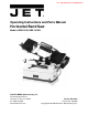
Uncrating and Cleanup Note: Read and understand the entire manual before attempting setup or operation. 1. Finish uncrating the saw and inspect for damage. Should any have occurred, contact your local distributor. 2. Remove all bolts attaching machine to shipping base. 3. Leave packing material between vise clamps and saw head intact until band saw has been lifted to its final position. 4. Clean all rust protected surfaces with kerosene or diesel oil to remove protective coating.
Figure 2 4. Carefully lift motor and line up holes in the motor mounting plate and the motor bracket. 5. Slide motor support shaft into motor mount bracket to hold the motor in place. 6. Fasten shaft with nut and washer. 7. Loosen strain relief nut on the motor junction box. Remove the junction box cover. Insert wire through strain relief and connect to the terminal strip using the diagram on the junction box cover. Tighten the strain relief nut and replace the junction box cover. 8.
To convert the HBS-916W from 115V to 230V, the following items will have to be changed: Main Motor – follow diagram inside junction box cover. Coolant Pump – Remove chip pan on front of saw, remove junction box cover on pump, and follow diagram inside junction box cover. Control Transformer – Open electrical panel on rear of base and change the fuse from 115V to 230V. Machine must always be correctly grounded.
7. Material to be cut must be securely held in vise. 8. Check to see that coolant level is adequate and turn on coolant pump if material to be cut requires it. Machine should be filled with four gallons of the proper coolant mixture. Follow the directions on the product maker’s label and fill the coolant tank through the chip tray area. 9. Do not start cut on a sharp edge. 10. Keep machine lubricated. See “Lubrication” section. Adjustments Adjusting Vise Square to the Blade 1.
Adjusting Feed Rate Rate of feed is adjusted by turning the cutting pressure control knob on the control panel. Rate of feed is important to band saw performance; excessive pressure may break the blade or stall the saw. Insufficient pressure rapidly dulls the blade. Material chips or shavings are the best indicator of proper speed and pressure. The ideal chip is thin, tightly curled, and warm to the touch. Chips that range from golden brown to black indicate excessive force.
9. Tension blade to approximately 25,000 lbs. of blade tension, as indicated on the blade tension indicator found on the tension wheel shaft housing. 10. Attach wire brush to the wire brush post with screw and washer. Adjust wire brush post so that brush just comes into contact with blade teeth. 11. Close all covers and guards and fasten securely. Connect machine to power and run freely for approximately two minutes. 12. Turn power off and re-check blade tension and wire brush adjustment.
Automatic Shut‐Off Adjustment The motor should shut off immediately after the blade has cut through the material and just before the head comes to rest on the horizontal stop bolt. If the machine continues to run after the workpiece has been fully cut, locate and adjust the micro switch mounting plate down. If the machine shuts off before the workpiece has been completely cut, move the micro switch mounting plate up. Thrust Roller Adjustment 1. Disconnect machine from the power source. 2.
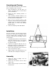
Bow Weight Adjustment Bow weight is one of the most important adjustments of the saw. If the bow weight is not set properly, one can expect poor performance, crooked cuts, tooth stripping, stalling, and the blade popping off the blade wheels. The hydraulic feed rate unit will not compensate for improper bow weight. Bow weight has been set at the factory and should not need any adjustment. If adjustment becomes necessary: 1. Disconnect machine from power source. 2. Turn on hydraulic valve (F, Figure 5). 3.
Maintenance Before doing maintenance on the machine, disconnect it from the electrical supply by pulling out the plug or switching off the main switch! Failure to comply may cause serious injury. Keep the band saw and the motor clean. If the power cord is worn, cut, or damaged in any way, have it replaced immediately. Lubrication Figure 12 All ball bearings are permanently lubricated and sealed. They require no further attention.
Base and Bed Assembly 16
Saw Arm Assembly – HBS‐916W 17
Saw Arm Assembly – HBS‐1018W 18
Parts List for HBS-916W, HBS-1018W Index No. Part No. Description Size Qty 1 .............. HBS916W-01 ..........Base (S/N 8081108 and lower) ............................................................ 1 ................ HBS916W-01A ........Base (S/N 8081109 and higher) ........................................................... 1 ................ HBS1018W-01.........Base (S/N 808718 and lower) .............................................................. 1 ................ HBS1018W-01A ......
Index No. Part No. Description Size Qty 39 ............ TS-1490041 ............Hex Cap Bolt ....................................................M8x25........................ 1 39-1 ......... TS-1551081 ............Lock Washer ....................................................8mm .......................... 1 39-2 ......... TS-1550061 ............Washer ............................................................8mm .......................... 1 40 ............ HBS916W-40 ..........Motor Tilt Plate .....
Index No. Part No. Description Size Qty ................ HBS916W-70A ........Electrical Panel Cover (S/N 8081109 and higher HBS-916W) ................ 1 ................ HBS1018W-70A ......Electrical Panel Cover (S/N 808719 and higher HBS-1018W) ................ 1 71 ............ HBS916W-71 ..........Fuse Block ......................................................................................... 2 ................ HBS916W-71A ........Fuse 3A ..........................................................
Index No. Part No. Description Size Qty 100-2 ....... TS-1551061 ............Lock Washer ....................................................M8 ............................. 2 101 .......... HBS916W-101.........Hose .................................................................................................. 1 101-1 ....... HBS916W-101-1......Hose .................................................................................................. 1 102 .......... HBS916W-102.........Support Shaft ...
Index No. Part No. Description Size Qty 127-1 ....... HBS916W-127-1......Eccentric Sleeve (inside)(HBS-916W) .................................................. 2 ................ HBS1018W-127-1 ....Eccentric Sleeve (inside)(HBS-1018W) ................................................ 2 128 .......... TS-1551061 ............Lock Washer ....................................................M8 ............................. 4 129 .......... TS-1504091 ............Hex Socket Cap Screw ..........................
Index No. Part No. Description Size Qty 157 .......... HBS916W-157.........Blade Guard ....................................................................................... 1 ................ HBS1018W-157A ....Blade Guard ....................................................................................... 1 157-1 ....... HBS1018W-157-1 ....Blade Guard - down ............................................................................ 1 157-2 ....... TS-1482021 ............Hex Cap Bolt .............
Index No. Part No. Description Size Qty 188 .......... TS-1524021 ............Set Screw ........................................................M8x10........................ 1 189 .......... HBS916W-189.........Extension Bar ..................................................................................... 1 190 .......... HBS916W-190.........Wheel Shaft ....................................................................................... 1 191 .......... HBS916W-191.........
Gear Speed Reducing Box Assembly 26
Parts List for Gear Speed Reducing Box Assembly Index No. Part No. Description Size Qty 1 .............. HBS916W-94-01......Oil Seal ............................................................35x55x8 mm............... 1 2 .............. HBS916W-94-02......Bearing ............................................................30207 ........................ 1 3 .............. HBS916W-94-03......Bearing ............................................................6207 .......................... 1 4 ..............
Electrical Connections – HBS-916W 28
Electrical Connections – HBS-1018W 29
NOTES 30
WALTER MEIER (Manufacturing) Inc. 427 New Sanford Road LaVergne, Tennessee 37086 Phone: 800-274-6848 www.waltermeier.