
User's Manual
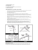


thermal barrier that can prevent the smoke from reaching an alarm mounted on the ceiling. In such units, install the smoke alarm on an
inside wall with the top edge of the alarm at a minimum of 4” (10 cm) and a maximum of 12” (30.5 cm) below the ceiling (see
Figure 1). If you are not sure about the insulation in your mobile home, or if you notice that the outer walls and ceiling are either hot
or cold, install the alarm on an inside wall. For minimum protection, install at least one alarm close to the bedrooms. For additional
protection, see SINGLE FLOOR PLAN in Figure 2.
WARNING: TEST YOUR SMOKE ALARM OPERATION AFTER R.V. OR MOBILE HOME VEHICLE HAS BEEN IN
STORAGE, BEFORE EACH TRIP AND AT LEAST ONCE A WEEK DURING USE.
2.LOCATIONS TO AVOID
• In the garage. Products of combustion are present when you start your automobile.
• Less than 4” (10cm) from the peak of an “A” frame type ceiling.
• In an area where the temperature may fall below 40ºF or rise above 100ºF, such as garages and unfinished attics.
• In dusty areas. Dust particles may cause nuisance alarm or a failure to alarm.
• In very humid areas. Moisture or steam can cause nuisance alarms.
• In insect-infested areas.
• Smoke alarms should not be installed within 3 ft (.9m) of the following: the door to a kitchen, the door to a bathroom
containing a tub or shower, forced air supply ducts used for heating or cooling, ceiling paddle or whole house ventilating fans,
or other high air flow areas.
• Kitchens. Normal cooking may cause nuisance alarms. If a kitchen alarm is desired, it should have an alarm silence feature or
be a photoelectric type.
• Near fluorescent lights, amateur radios, electrical equipment or other devices known to transmit in the RF band. Electronic
“noise” may cause nuisance alarms.
• Near large metal surfaces and bundles of wire.
Smoke alarms are not to be used with detector guards unless the combination (alarm and guard) have been evaluated and found
suitable for that purpose.
3. INSTALLATION INSTRUCTIONS
WIRELESS INTERCONNECT SETUP
1. Remove your new Kidde Wireless Interconnect devices from their
respective packages and place them in front of you.
DO NOT PLUG THEM IN OR INSTALL THE BATTERIES.
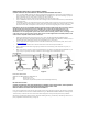
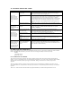
2. Find the 8-position dipswitch located on the back of each device. For this
model, the dipswitch is located under the battery door (see Figure 4).
3. Select one of the units. You will define the ID of your system by
positioning the switches of the dipswitch in a random pattern. The ID will
need to be the same for each alarm or accessory. This ID will differentiate
your alarm system from similar systems nearby. DO NOT USE THE
DEFAULT ID YOUR UNITS ARE SHIPPED WITH!
4. Using a pen or pencil, change the switches in each of the Kidde Wireless
devices to match the pattern you selected in step 3. Insure that the sequence
is not reversed.
5. Power each unit after setting the ID by installing the battery. The alarms
read the ID only when they are first powered up. Any changes to the switches after the unit is powered will not be recognized
and will require the units to be disconnected from power for a minimum of 30 seconds before powering the units up again.
6. Push and hold the test button on each unit for at least 5 seconds or until all the alarms produce an alarm signal. If all the alarms
do not produce an alarm signal refer to the trouble-shooting section at the end of the manual.
CAUTION: Due to the loudness of the alarm, always stand an arms length away from the unit when testing.
7. Install the alarms in accordance with the owner's manual and repeat step 6. Since WIRELESS communication can be
interrupted by a number of factors, you must test your alarms weekly to ensure proper communication between alarms.
8. Read the owner’s manual and keep it in a safe place for future reference.
If your Wireless smoke alarms enter alarm mode, first check to see if there is a fire. If a fire does not exist, and
the test buttons have not been activated on any of the units, it is likely that you are receiving interference from a
similar system nearby. In this case, repeat the above steps and select a different dipswitch pattern, making sure
to disconnect power and remove the batteries before changing the switch positions.
WIRING REQUIREMENTS
• This smoke alarm should be installed on a U.L. listed or recognized junction box. All connections should be made by a
qualified electrician and must conform to article 760 of the U.S. National Electrical Code, NFPA 72 and/or any other codes
having jurisdiction in your area.
• The appropriate power source is 120 Volt A.C. Single Phase supplied from a non-switchable circuit that is not protected by a
ground fault interrupter.
WARNING: This alarm cannot be operated on power derived from a square wave or modified square wave inverter. These types of
inverters are sometimes used to supply power to the structure in off grid installations, such as solar or wind derived power sources.
These power sources produce high peak voltages that will damage the alarm.
Figure 4