ROTARY TILLER REARTINE TILLER ilnlu0uulllc,Pnftfl||r|0tw orlly sptctRmW tvt0tltlr Tifrffibeads are nor pr'perlv seated, arrpnssure ovbr 34pgican ciuie ttre ilil hilertffi ih; assembly with lq_a\pbdeforielullicient toartae iiri,iiiolTiiii'i'ijii.iiii. ,beads Make certain rimrscorrect diarireter and type.G.n rim,lubricat0,,rim, ilvgiecotaI$iildiil;hp :l9"t9:8"*1,'"ll'^,^{t,ttt'$eno_fl beads. notstand ovTrffitltffi tatrng-ffiiffi .Do : manufacturer's inflation recommendetis["-.^:::, -.
GONTENTS Generol Introduction SofetyTips InitiolServicing Controlsond Operotion StortingYourRotoryTiiler Adiustments Seruicingond Mointenqnce Storoge TillerPorts TillerPortsList Chqin Cose Ports Choin Cose PortsList Howto Order Replocementports 3 3 4 4 5 6 I 11 12&14 r 3 &1 5 16 17 20 IMpoRTANT!Recordthe unit model number ond its seriol number on the bock poge of this monuol for fulurereterencewhen orderingrepoir portsor identificotionif unit is lostor stolen.
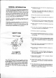
GENERAL INTRODUCTION ThisOwneis Guide hos been especiolly prepored lo provide the informotion needed to op'eiote your tii ler with greoler sotisfoction.Reod this'Owne/i Guide ond the engine inslrucfionscorefully. Be sure you know whot the controls ore for ond how they o[ergte: Ilte core your tiiler requiresis smoil, but'imior_ tont. Keep it cteon ond weit tubricofed. Witn prcjber core ond operotion,os exploined in this monuof, you will obtoin long ond efficientservice. This.tiller, is .
IN I T I A L S E R V I C I NG 1. Before storling the engine, refer fo the engine insfructions.Be cerloin lhe the engine cronkcose is filled with the proper type oil ond thot oll engine serviceinstructions hove been followedcompletely. CLUTCHCONTROLLEVER THROTTLE CONTROL& ENGINE STOP LEVER 2. Fillfuel tonk wilh o cleon, fresh,leod-free or leoded "regulor'' grode of outomotive gosoline. Do not mix oil with gosoline. All nuls ond bolts should be checked ond tightened during lhe firsttwo (2) hoursof use.
Whenthe handlebar is in tnansportlocation,fhe clufch control lever will only operofe by pulling the lever bock. Thisengoges the drive to the wheels ond the tiller moves forword of tronsporl speed. When releosed, fhe control lever refurnsto neulrol. DEPTHCONTROLLEVER GAUTION:Do nor adiust rilling depth wfth rhe tines rotatang.Place clutch control leyer in the neutral position before makhrgadiustments of depth control. SHAULOWEST SETTING The depth conirol lever is the "key" to eosy tilling operotion.
ADJUSTMENTS CAUTION:Never ofiempt to moke-odjustments on fhe lillerwhile the engine is running.Alwoysstop lhe engine ond disconneclthe wirelrom tn6 spoit plug before ottemplingto moke odjustments. ROTATE CLAMP CAP SCRE\ BELT ADJUSTMENTS TINE DBIVE BELT The tine drive belt, which is the outer be[, is odjusted by cop screws (Figuie4) onct roto_ l9_9s9ningthe ctomp qnd ang me enflre cose tine ossembly.
HANDLECONTROLLEVERADJUSTMENT The hondle control odjustmenl(Figure7) hos been set for proper operotion ond should not need to be odiusfed.Shouldthe hondle control lever (Figure7) become loose ofter mony hoursof operolion,tighlen the odjustmenlnul only enough lo eliminoteony excess movementin the hondle confrol lever. NUT ADJUSTMENT CAUTION:Do nol overtighlen odjuslmenf nut. This moy resultin foilureof hondle bor lotch systemlo fully engoge ond hold hondle in desired position.
SERVIGINGAND MAINTENANGE Thebesf ossuronceyou hove of geiling the mosl de_ pendoble service from your tiller is to keep the unit cleon, free of rust,ond well lubricoted. Check bolts often lo be sure they ore kept tight. Whenthe tiller is not being used,it shouldbe storedin o dry ploce out of lhe weother. LUBRICATION 1. Engine:Referlo engine operoting instructions ond requirementsfor oll engine lubricotion. 2.
4(l ) ' . .q...-<- ___=/ 4ffi' Y a-\ I \ ', l*_./ lilll, t Fte.12 To odd lubricont to eilher choin cose it is necessory to tip liller on its lefi side lo expose tevel ptugs of eocn cose. Add sufficient teod bose (Ep)SAEtaO neovy duty oil (Port4890) to bring to propdr oit tevet. fore oiling ottempt lo cleon off oreo lo be lubricoled. A. The4 idler pulleys. B. Thehondle plunger shoflond disc. C. The conirol rod swivels. 3.
\ /'/ | I .z -.1I /1 wHEEL DRtvE cAsEpuLLEy ).. '/ / /\ -\ TlNi DRTVEBELT / R E TA IN IN G R IN G TINEDRIVECASEPULLEY ptN BELT GUTDE tl8:g!\|rNGR|N-G/ \_- \r TINEDRIVE ,,.,} 'O'.'* BELIGUIDE \,, ARM L|NK -__--.---IDLER COTTERPIN F re . 1 3 BEIT REPLACEMENT Thebells on thistiller.werespecificollydesigned ond enginee.redto provide long, trouble_freeservice.
STOBAGE For short lerm storoge,cleon the filler off ond store In o dry ploce. 3 Runengine untilil stops. 1 lf tiller is not lo be used for on extended period of time, service tiller completely onOJi"re it' in -dry o ploce. 1 I, 1 Feler to the engine instructions for engine storoge inslructions. i 2. Droingosolinefrom fuel tonk. 4. Cover exposed metol surfoceswith o t hin coot of engineoil. Lub.ricoteper insfructions under ,,servicingond Moinlenonce".
HANDLE& CONTROL PARTS q FI c AL-q o.,-@ ^"-?t" 12 ,.
HANDLE & CONTROLSPARTSLIST RE F . LET. A B C D E F G H I J K L M N o P R S T U V W X z AD AE AF AG AH AI AJ AK AL AM AN AO AP AQ AR AS AT AU AV AW AX AY M BA PART N O. 200469 200470 1'183 200612 2 0 0 11 0 200066 2OO473 200460 200420 200074 33580 2OO075 200323 200768 2 O O1 7 9 200177 200195 200196 200242 200055 200324 200462 33595 2 OOO4 5 2679 200034 D E S C R IP TION T u n n e l A ssembl y Handle Assembly G ri p .. Slide . S p ri n g C o n tro l R od .. Pivot Assembly . . . P a w l A s sembl y.. ..
FRAMEAND DRIUE PARTS €[--cl .B P ,BQ ,K ./fl- a:,t -;^A 9@/---,"u BN BO J BG BF GJ '-- AZ H '/cL ,fu'"'o -6 ,i^ '@ft{ %c=s t7"30,-- 6tt cc ==Eg :?g rr€ ;tr^ffieiSi: s_; #tury -AO AP l s 'l:a- t-ca " -BZ,6\}-V 22tgffiD 6a-6 P artN o.13938 . P artN o.13255. M____-_ N 14 CANS OFTOUCH-UPSPRAY PAINTARE AVAILABLEBY ORDERING: . . . . . . G r ay .. . . . . .
FRAMEAND DRIVE PARTS LIST Ref. Let. A B c D E F G H I J K L M N o P o R S T U V W x z AA AB AC AD AE AF AG AH l- AI AJ AK AL AM AN AO AP AQ AR AS AT AU AV AW AX AY Part No. Description OtV- 208139 FrameAssembly- R.H. 1 2O814O FrameAssembly- L.H. 1 2O O O 71C o u n te rWe i g h.... t ... 30 2O O A 78C o u n te rWe i g h.... t 8 200165 DepthControlAssembly 1 208810 S k i d As s e mb l y ..... 1 j 2OO184 Support Assembly 24897 Handle z 2O O 197 S p ri n g . . ...... 1 'l 200063 EnginePulley .
GHAINCASEPABTS Io reploce oll choin cose seols ond dosketsorder PortNo.89428. To reploce entile choin cose less lines drder Pod No.
GHAIN GASEPARTSLIST REF. LET. A B c {.**t.r*' D E F G H I J K L M N o P o B S T U V W X Y z PART N O. D E S C R IP TION 208162 ChainCase Ass'y.- R.H.w/Bearings. . . . 208163 ChainCase Ass'y.- L.H.w/Bearings 1054 Seal - Tine Shaft. . 208176 Seal - InputShaft . 208052 Gasket 208051 Chain - Lcwer . 208177 Chain - Upper . 2 0 8 1 8 6 In p u tSh a ftA ss' y. ... 208178 SprocketAss'y.w/Bearings ..... 4O2O ldler Sleeve 208181 Tine ShaftAss'y.. . . 2O81U SpacerCup 39108 Shim - Gear. .
ri{/Hff6" OPERATING AND MAINTENANCE INSTRUCTIONS MODELSERIES 100200to 100299 130200to 131299 IN THE INTERESTOF SAFETY DO NOT RUN ENGTNEAT EXCESSIVESPEEDS.Operatingan engine at excessivespeedsincreasesthe hazard of personalinjury. DO NOT TAM PERW I TH PARTSW HI CH M AY I N C R E A S ET H E G O V E R N E DS P E E D . For rotary lawnmowersafety,A.N.S.l.StandardSafetySpecificationsfor Power Lawn Mowersspecifya maximum blade tip speed of 19,000feet per minute (96.
BEFORESTARTING SPARK PL UG TO BATTERY VI A S TA R TE R S WITC H R E A D TH E OP E R A TIN GIN S TR U C TI O NSO F TH E E OU IP ME N TTH IS E N GIN E PO WERS U se a hi gh qual i tydetergentoi l cl assi fi ed" For Ser viceSC, S D , S E or MS ." D etergentoi l s keepthe engineileaner and retardthe formati onof gum and varni shdeposit s.Not hing shoul d be added to the recommendedoi l .
necessaryw i th chokeopenedsl i ghtl y.Whenenginest ar t s' open choke gradual l Y . STARTING S t ar t ,s t or e and fu e l e n g i n e i n a l e v e l p o s i ti on. E NG I N E - En g i n e ma y b e e q u i p p edw i th ei ther Choke-A-Maticor Lever-Trolcontrols. MA NUA L CHO K E: P u l l c h o k e a s i l l u s tra te d . C HO K E - A - M A T ICa n d L EV ER -T R OL L- Mo vecontrol sas far as possroletoward "Choke" or Start.
MAINTENANCE CHECK OIL LEVEL regularly - after each five hours ol operatio-n-trSFE orL LEVEL ts MAtNTAINED. CHANGE OIL after first five hours of operation.Thereafter change every25 hours of operation.Removeoil drain plug a n d d r ain oil while e n g i n e i s w a rm. R e p l a c ed ra i n pl ug. R e mov eoil f ill plug o r o i l -m i n d e ra n d re fi l lw i th n ew oi l of p ro p e r gr ; de. Repla c eo i l fi l l p l u g o r o i l -mi n d e r.
CLEAN COOLING SYSTEII - Grass, chaff or dirt may the air cooling system, @d especiallyafter prolongedservicecutting dry grass.Yearly or every 100 hours, whichever occurs first, remove the blower housing and clean the areas shown -to avoid overspeeding, overheating and engine damage. Clean more often if necessary. CL EAN OUT CHAF F AN D DIRT DANGER: Periodically clean muffler area to remove all gr as s ,dir t and co mb u s ti b l ed e b ri s . SPARK PLUG - Clean and reset gap at .
ment on whic h th e e n g i n e i s u s e d , s p e ci fi es the top gov er ned no l o a d s p e e d a t w h i c h th e e n gi ne may be oper at ed.DO N O T EX C E EDth i s s p e e d . exceed85%of this rating. Engine power will decrease3%% for each 1,000feet (304.8m) above sea level and 1o/otor each 10o above 600 F (16" C ). ln some areas,local law reqtliresthe use of a resistorspark pl ug so as to suppressi gni ti on si gnal s.