
Installation Instructions
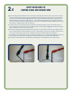
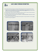
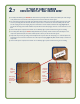
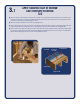
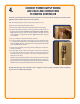


Figure 10a
Figure 10b
Sensor (bulb)
Tail splice
SECURE SENSOR WIRE*,
TAIL SPLICE AND ANY LOOSE HEATING CABLE
z Sinceaoortemperaturesensormustbeused,positiontheSensor Wire midway between two adjacent Heating Cable runs that are
spaced 3" apart. The sensor (bulb) of the sensor wire should extend at least 6" in from the Return Loop and lay not closer than 1
1
/
2
" to
a heating cable.
z Due to the slightly larger diameter of the Tail Spliceandthebulbofthesensorwire,removeapproximately¼"ofsub-oormaterial
below the splice connection and sensor bulb and secure with
Ribbon Strapping and/or plastic clips in the same manner described in Step 5 for the Cold Lead Splice. Remove all debris after this step
to avoid cable damage (Figure 10a and 10b).
z Secure heating cable near the End‑of‑Run with the clips provided or by stapling 2" lengths of Cable Strappingtotheoor.ENSURE
THAT STAPLES DO NOT PENETRATE THE CABLE OR SENSOR WIRE!
z After the cable is secured, repeat test of the system as per section 2.4.
*Sensor wire is supplied with thermostat
2.8