
Installation Instructions

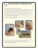

VERIFY RESISTANCE OF
HEATING CABLE AND SENSOR WIRE
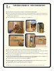
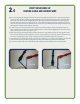
z Before proceeding with cable installation, measure the resistance of the heating cable and sensor wire to ensure that no damage has
occurred to either cable during shipment and subsequent handling. To measure heating cable resistance, connect the two ohmmeter
leads to each of the cold lead conductors (Figure 5a). Record the reading in the Warm Tiles Cable Resistance Log provided in the
DFTCableGuide.Verifythattheohmreadingiswithin-5%/+10%ofthefactorylistingappearingonthecoldleadtag.Tomeasure
sensor wire resistance, connect the two ohmmeter leads to each of sensor wire conductors. Record the reading in the resistance log
andverifythatthereadingisbetween7,000and14,000ohms.
z To make sure there is no contact between the copper ground braid and heating conductors, connect one ohmmeter lead to the
copper ground braid and the other lead to the two cold lead conductors connected together (Figure 5b). The ohmmeter will display
either“I”forinnityor“OL”foroverloadoropencircuit.
z Finish up your testing by conducting an insulation resistance test: Connect a mega ohmmeter between the copper ground braid and
thetwocoldleadconductorsconnectedtogether.Setthetesterat500V(minimum)andmeasuretheinsulationresistance.Theresis-
tancemustbe10MegaOhmsminimum.Thistestisdesignedtodetectminutebreaksthroughoutthecableinsulation.
z Thevericationstepsasexplainedaboveshouldberepeatedaftercompletingstep3.1or3.2(aftercableinstallation)andbeforenal
powerconnectioninstep4(afteroorcovering).RecordallreadingsintheresistancelogprovidedinDFTCableGuide.
z Iftheresistanceofeithercabledoesnotfallwithinthespeciedrange,pleasecontactEasyHeattollfreeat1-800-537-4732.
2.4
Figure 5a Figure 5b