Installation Instructions for DFT cable sets
WARNING! Electric Shock/Fire Hazard Read the following warnings and instructions provided before attempting installation. Failure to do so could result in cable failure, improper system operation, property damage, bodily injury or death. Failure to follow the warnings and instructions will also void the warranty. 1. Electrical inspection may be required before, during and/or after installation of the Warm Tiles system.
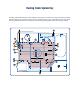
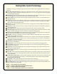
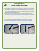
Heating Cable System Key The DFT Cable Guide and DFT Cable Installation Instructions introduce terminology to identify and explain key DFT Cable Kit components and how they are installed. These terms are italicized each time they appear and are graphically illustrated and explained in the following Heating Cable System Terminology and Key.
Heating Cable System Terminology The following terms may appear frequently throughout these instructions in italicized text. Each is graphically illustrated in the key illustration above. 1 Alternating Heating Cable Spacing. The Heating Cable configuration used for floors above unheated areas and concrete slabs. Cable is laced through the strapping at repeating spacing intervals of 11/2"‑3"‑11/2"‑3", etc. using the tabs of the Cable Strapping (see also Standard Heating Cable Spacing). 2 Border Dimension.
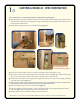
1.1 electrical rough-in : new construction For new construction it is recommended that rough-in be completed before drywalling begins. z Determine the appropriate location and height for the Electrical Connection Box* (ECB). Consider proximity to other outlet boxes, ease of routing Cold Lead to the Heated Area, and accessibility of the heating controller during normal use. Typically the cold lead enters the same wall cavity in which the ECB is located.
1.2 electrical rough-in : remodeling project For a remodeling project, complete the electrical rough-in as follows: z Determine the appropriate location and height for the Electrical Connection Box* (ECB). Consider proximity to other outlet boxes, ease of routing Cold Lead to the Heated Area, and accessibility to a planned heating controller. The cold lead should enter the same wall cavity in which the ECB is located. Contact your local electrical inspection authority for electrical code requirements.
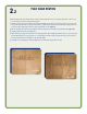
2.1 verify size of heated area Drywall, fixtures and vanities removed for illustrative purposes. z Confirm the cable selected will provide the correct coverage by measuring your room floor and determining the square footage to be heated. This is your Heated Area. Areas under cabinets or fixtures (toilets, sinks, tubs, etc.) should NOT be included (Figure 2).
2.2 plan cable routing z Before installing cable, ensure that all surfaces on which the Heating Cable will lie are free of any sharp edges, debris or other restrictions that may cut or otherwise damage the heating cable. z Carefully measure and locate the mid-point of the Heated Area (NOTE: This may differ from the linear mid-point from one end of the room to the other). This will be a useful reference line later, as it should coincide with the "Half of Cable Marker".
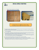
2.3 install Metal strapping Distance between adjacent rows of strapping Figure 4b Figure 4a z Each cable kit contains a suitable number of rolls of Cable Strapping, the unique cable strapping system developed by EasyHeat for enabling fast, problem-free heating cable installation. z Install the cable strapping at 30" to 36" intervals for Standard Heating Cable Spacing or at 18" to 24" intervals for Alternating Heating Cable Spacing (Figure 4a).
2.4 VERIFY RESISTANCE OF HEATING CABLE AND SENSOR WIRE z Before proceeding with cable installation, measure the resistance of the heating cable and sensor wire to ensure that no damage has occurred to either cable during shipment and subsequent handling. To measure heating cable resistance, connect the two ohmmeter leads to each of the cold lead conductors (Figure 5a). Record the reading in the Warm Tiles Cable Resistance Log provided in the DFT Cable Guide.
2.5 pull cold lead and sensor wire into ECB; secure the Cold Lead Splice z It is important to properly de-coil the cable to prevent twisting. Insert a rod (such as a broom handle) through the cable spool hub and support on a ladder or equivalent (Figure 6a). z Pull the Cold Lead from the spool, and using fish cords, pull it through the ¾" hole in the sill plate, up through the wall cavity and into the ECB.
2.6 lace cable through strapping z Place Heating Cable (section with clear outer covering and visible underlying copper braid) at and angle between the tabs and straighten to secure in place (Fig. 8a & b). Proceed with cable installation following the layout outlined on the floor earlier, space at appropriate intervals (at 3" or every second slot for Standard Heating Cable Spacing, [Fig. 7a] and every 3" - 1 1/2" - 3" - 1 1/2" alternating slot for Alternating Heating Cable Spacing [Fig. 7b].
2.7 if “half of cable” marker does not meet at “half heated area” z If the Half of Cable Marker appears BEFORE the Half-of-Area-Line previously marked on the floor, there will likely be a cable shortage at the planned end of run, the amount of which depends on how far before the line the marker appears. z For a cable shortage, consider the low traffic areas and Border Dimension. Cable can be conserved by avoiding placement in low traffic areas or by increasing the border dimension.
2.8 secure sensor wire*, tail splice and any loose heating cable z Since a floor temperature sensor must be used, position the Sensor Wire midway between two adjacent Heating Cable runs that are spaced 3" apart. The sensor (bulb) of the sensor wire should extend at least 6" in from the Return Loop and lay not closer than 11/2" to a heating cable.
3.1 apply scratch coat of mortar and complete flooring Tile z Once the cables have been installed on the floor, apply a ‘scratch coat of cement-based mortar uniformly over the entire floor area, such that the heating cables are completely embedded. Self-leveling cement-based mortar compounds may be most appropriate for this procedure, but consult with your flooring supplier for advice. z Follow the compound manufacturer’s instructions for preparing the mix.
3.2 apply scratch coat of mortar and complete flooring Laminate z Once the cables have been installed on the floor, apply a ‘scratch coat of cement-based mortar uniformly over the entire floor area, such that the heating cables are completely embedded. Self-leveling cement-based mortar compounds may be most appropriate for this procedure, but consult with your flooring supplier for advice. z Follow the compound manufacturer’s instructions for preparing the mix.
4. connect power supply wiring and cold lead conductors to heating controller Installation of any heating controller and associated wiring must be in accordance with the manufacturer’s instructions and all applicable national and local electrical codes and ordinances. Before proceeding with final power connection, repeat test of the system as per 2.4. Prepare for power supply wiring connections as follows z Ensure the power supply branch circuit has been disconnected and de-energized.
Should you have further questions, comments or concerns regarding Warm Tiles DFT Cable, please call EasyHeat’s Technical Department toll-free: • In the United States, 800/523-7636 • In Canada, 800/794-3766. USA 2 Connecticut South Drive East Granby, CT 06026 Tel. (800) 523-7636 Fax: (800) 824-7345 CANADA 99 Union St. Elmira, Ont. N3B 3L7 Tel. (800) 794 3766 Fax: (800) 361-4574 floor warming • snow melting • pipe tracing • roof & gutter de-icing • thermal storage 14073-001 Rev.