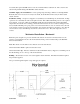
THE NEXT GENERATION OF THE INDUSTRY STANDARD PLENUM HEATER Installation & Operating Instructions EM-WU(WD)***S*-SL1 Series – One Stage HP or One or Two Stage AC See specification page for model number breakdown and details Dual Heat Combinations Heat pump – WarmFlo Select – gas/oil furnace, 1 or 2 burner stage, single speed or ECM blower AC – WarmFlo Select – gas/oil furnace, 1 or 2 burner stage, single speed or ECM blower AC, 2 stage – WarmFlo Select – gas/oil furnace, 1 or 2 burner stage,
Table of Contents Specification 1 Product Dimensions 1 Introduction 2 Installation Requirements 3 Mechanical Installation Upflow 4 Downflow 7 Horizontal 8 Electrical Hookup 9 Additional Hookup or Special System Equipment Concerns 12 Field Setup or Programming 14 Operation Indicators 17 Stat Override Timer (SOT) 18 Handheld Analyzer/Laptop Software 18 Troubleshooting 18 Manual Reset 20 System Airflow 20 Installation Checkout 21 Drawings Included: 08/04/2008 EH709 EH712 EI
Specification HP or AC – One Stage Equipment Model Number EM-W*102S+ EM-W*153S+ EM-W*204S+ EM-W*254S8 kW rating BTUH Voltage/Phase Circuit Breaker Source Feed Elements Max. Temp.
Introduction The intended application for this product is summarized on the cover page. If this does not fit your application needs or HVAC system design, do not modify or attempt to use this model other than its designed and intended usage.
Installation Requirements 1. All installation work must be performed by trained, qualified contractors or technicians. Electro Industries, Inc., sponsors installation and service schools to assist the installer. Visit our web site at electromn.com for upcoming service schools. WARNING ALL ELECTRICAL WIRING MUST BE IN ACCORDANCE WITH NATIONAL ELECTRIC CODE AND LOCAL ELECTRIC CODES, ORDINANCES, AND REGULATIONS. WARNING OBSERVE ELECTRIC POLARITY AND WIRING COLORS.
Mechanical Installation – Upflow For downflow or horizontal see appropriate section. This upflow section provides more illustrations and details. The installer should review this section and then relate the comments under downflow or horizontal as they apply. This section assumes there is either an A/C or HP A-coil, if there is no coil in the plenum simply proceed without visualizing the presence of the A-coil. Typically this means the WarmFlo Select unit will be directly above the furnace cabinet.
Step 2 Measure plenum width and depth a. Step 1 determines facing side (hole cut decision) b. Width 17” or less – 15” model 18” or 19” – 18” model 20” to 22” – use side baffles as detailed in C-1 23” or greater – must field construct baffling as shown in C-2 c. Depth 20” or less – no baffling 20” or greater – need rear baffling as detailed in C-2 Step 3 Cut insert hole a.
Step 4 Add necessary baffling a. See Step 2 for determination and if required Step 5 Insert unit and bolt in place a. Extend center V deflector to plenum depth b. Do not drill into refrigerant lines c. Note airflow decal d. Seal as required Step 6 Install WarmFlo sensors a. Outdoor (OT) – extend to best location, mount with tip up Attempt to shade from direct sun, north side preferred See electrical section with additional sensor details b.
Airflow Page 1 specification chart shows maximum temperature rise at 55° F. This is simply good HVAC practice and duct works/furnace blower design. The WarmFlo Select controller and its sensing will take care of itself but there is more to the story. It is true that the WarmFlo Select modulating control and the supply sensor adjust the electric heat or element capacity based upon temperature.
necessarily line up the WarmFlo Select control box with the furnace cabinet front. The concern is the cutout in the plenum mating with WarmFlo Select elements. WarmFlo supply sensor installation – notice spacing and positioning comments on drawing EA104. Basically this sensor needs to be in a major air stream, about 20 airflow inches away from the actual electric element. Installation, wiring – except for a shipped loose (included) second hi-limit probe, all electrical, hookup, operation, etc.
Electrical Hookup WARNING DISCONNECT ALL ELECTRICAL POWER BEFORE ELECTRICALLY CONNECTING OR SERVICING THE UNIT. FAILURE TO DISCONNECT THE ELECTRICAL POWER BEFORE WORKING ON THIS PRODUCT CAN CREATE A HAZARD LEADING TO PERSONAL INJURY OR DEATH. Line Voltage The nameplate and/or Installation and Operating Manual specification page provides kW rating and operating current requirements. Select the proper wire size to comply with your type of wire routing and NEC field wiring requirements.
Use care in selecting location so the sensor does not pick up false temperature from the heat pump outdoor unit, from refrigerant line sets, dryer vent, reflection off of steel siding, etc. Also do not install the sensor in a plastic box because it will falsely trap and pick up radiant sun temperature. Other Sensor Related Comments The factory supplied OT cable is 25 feet. If additional cable length is required, you must use the following rules for extending the cable.
to the furnace Y2. However, if there is a desire to control the furnace Y2 based on WarmFlo temperature sensing, request special procedure (EH811) and the addition of EE-5053 relay for the furnace high speed function. Utility Load Control If utility load control applies, remove the blue jumper from the bottom left terminal block and connect the utility NC contact receiver or device. If opposite control logic is required, contact factory for other wiring instructions.
Additional Hookup or Special System Equipment Concerns Special Oil Furnace Comment This controller is designed to interface directly with a furnace fan center containing 24-volt transformer (40VA or larger), blower relay, and a “W” function to operate the furnace.
Load Control, Other Products or Hardware If there is a need to “pass on” the utility load control receiver function to other heating equipment, radiant floor boiler, peak interrupter, etc; there is an isolated contact on this control board. Locate tabs COM/EL/SB. In the electric mode there is an isolated contact between COM and EL. This contact is for low voltage only, 1-amp maximum. Note: There may be a 1 or 2 minute delay between this relay contact action and the actual load control receiver.
Field Setup or Programming It is extremely important the installer properly goes through this section and sets up the various switches to match the installation. Warning: Power-down reset required whenever changing any of the switch positions on the back side of the board. HP Reversing Valve Logic Since this control board creates the reversing valve control wire for the heat pump, it is important the installer select the required logic for the heat pump installed.
Important Located on the WF+ board is a firmware chip that, along with the position of the application selection dial, determines a specific set of defaults. However, this can be programmed (altered) with optional plugin WarmFlo Analyzer (WF-ANZ7). WARNING ADJUSTING THE APPLICATION SELECTION DIAL WILL ERASE ALL SPECIAL PROGRAMMING CHANGES. Switchover Temperature (SW OVER) Select the temperature to ODT or interrupt the heat pump outdoor unit.
Emergency, Remote Switch If there is a need and the desire to have additional override switch or operation, use this information. Comment: The front panel normal/standby switch allows direct override to gas furnace independent of any other setup or load control condition. Note the front panel statement about cooling. E-tab or E-WF tab – supplying a remote switch from stat W to this tab activates all electric stages on. In essence, this is a WarmFlo logic and WarmFlo sensor bypass.
Operation Indicators Front Panel LED’s - Hi-limit – when the hi-limit probe (automatic reset or manual reset) opens this top red LED is on. The electric elements will be interrupted via a safety relay circuit whenever this HL LED is illuminated. PWR ON – indicates good fuse and 24-volt power source from the furnace terminal block. EL mode – this illuminates during electric heat function.
Stat Override Timer (SOT) This is a field option internal timer which can be field programmed with WF analyzer to select a roomstat cycle run time. If this downloaded run time (typically 30 minutes) is exceeded before the thermostat is satisfied, the system automatically switches to either full electric elements or standby. - SOT S – this is the longer set timer which allows transfer to standby if something might have happened to the electric system unmonitored.
Operational Conditions Which May Prevent Standby or Gas On 1. No call for heat - T-call LED is off 2. LED EL ON mode- utility is not controlling or front panel is not in override 3. Somehow stat terminal block Y is also energized or at 24 volts 4. Board K1 or K2 open/inoperative 5. Hang-up - power down, 10 seconds, power up Operational Conditions Which May Prevent EL Stages On (No Stage LED’s) 1. No call for heat - T-call LED is off 2. In standby mode, see previous section 3.
Bad sensor, operating default condition – the detection of bad sensor forces the controller to a fixed stage operation.
Installation Checkout Insert plenum thermometer 6” to 8” above the electric element section, position to measure the warm air from the electric elements. Proceed with the following procedure, observing the various staging action, element power current, and the outlet temperature. Verify controller setup dial switch settings per previous section. For this test, set the minimum warm air switch to #7. Return to previous setting at the end.
Electro Industries, Inc. Limited Product Warranty Effective October 1, 2007 Electro Industries, Inc. warrants to the original owner, at the original installation site, for a period of two (2) years from date of installation, that the product and product parts manufactured by Electro Industries are free from manufacturing defects in materials and workmanship, when used under normal conditions and when such product has not been modified or changed in any manner after leaving the plant of Electro Industries.
THESE WARRANTIES DO NOT COVER: 1. Costs for labor for removal and reinstallation of an alleged defective product or product parts, transportation to Electro Industries, and any other materials necessary to perform the exchange, except as stated in this warranty. Replacement material will be invoiced to the distributor in the usual manner and will be subject to adjustment upon verification of defect. 2.