
Instructions / Assembly


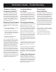

The Heating Element
The Heating Element consists of two copper alloy resistance wires
covered by Flouropolymer insulation. A braided metal surrounds
the primary Flouropolymer insulation and serves as ground sheath.
The Heating Element (A) attached with tape (C) in a serpentine
pattern to a exible Fiberglass Mesh (B). The Fiberglass Mesh is
designed to keep the Heating Element evenly spaced throughout
the roll. The cold lead return wire is factory installed at one end
of the Heating Mat and must run back to the power supply along
the perimeter of the heated space. The power lead (D) is 22-feet
in length. The lead is spliced to the Heating Element (E) at the
factory. If necessary, this lead wire may be shortened. Please
note the thickness of the factory splice and cold lead and plan
accordingly. Both the factory splices and the Heating Element must
be completely embedded in thinset or self-leveling underlayment
Floor Sensor
(not required for all systems)
Temperature sensor wire must be tested before and after installation
and must measure between 8k to 18k ohm for temperatures
between 68-86 F (20-30C). This measurement must be done with
a digital ohm meter, set to the 20k range. Beware of self-ranging
meters and analog meters.
Systems using a nSpiration Series control require a Floor Sensor
(F). This Sensor is embedded in the oor and monitors the oor
temperature. The Floor Sensor should be centered in between
2 resistance wires leaving approximately 1.5” on either side and
extend about 6” into the heated area. Avoid placing the sensor in
an area affected by a draft, a radiator or the sun. Must be installed
if using a thermostat. Some people choose to install a second
(Backup) sensor. For an additional cost you may purchase a
second sensor. NEVER run the sensor wire over, under, or next to
a heating wire. Sensor wires can touch the non-heating cold lead,
but must not run next to the lead for more than a couple of inches
and never run in the same conduit as the cold leads.
Heating Mats: Types and Sizes
Mats are rated at 15-watts per square foot and vary in size. Each
mat is designed to draw a specic amount of electricity and
therefore produce the proper amount of heat based on its size. For
this reason, the mat can never be shortened to make a proper t.
Working with the Heating Mat
The “Lead Wire” on the mat is designed to travel back to the control
device location. These wires do not heat. All connections are made
at this point.
Separating the Heating Element
from the Mesh
During the installation, you may need to separate the Heating
Element from the Fiberglass Mesh. This can be done provided
the Heating Element is not cut and the shielding is not nicked or
punctured.
E
F
G
WarmlyYours Floor Heating System.
A. Heating Element
B. Fiberglass Mesh
C. Drain Hole
D. Cold Lead Wire
E. Factory Splice
F. Floor Sensor
(optional)
G. End Cap
C/O INDIA Made by Thermopads Pvt. Ltd. for WarmlyYours.com Inc.
ENREGISTRE
LISTED
C
US
RADIANT HEATING PANEL UNIT
UNITE DE PLANCHER
CHAUFFANT ELECTRIQUE
8PA5
TempZone Electric Floor
Heating Panel
Plancher Chauffant Electrique
For installation in an
adhesive bed, self leveling or
mortar cement
Installation avec ciment, mortier
colle ou colle a carrelage
SKU S/NO
Resistance / Ohm Spez. output W/sqf
Puissance au pied carre : 15 W
Core to Core : 105.3 Ohm Voltage : 120V/60 Hz
Tension a Te nsion Length / ft
Grd Sheath to Grd Sheath : 1.02 Ohm Longueur en pieds : 9
Prise de terre a Pdt Width / ft
Largeur en pieds : 1.0
Output Unit W : 135
Puissance de l’unite
Secondary
Flouropolymer
Insulation
Primary
Flouropolymer
Insulation
Solid
Conductor
Wire
Metal Braiding
Connected to Ground
The Heating Mat
3