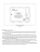
Automatic Snow/Ice Melting System Control Panel MODEL SCP-120 (APS-3C) SNOW SWITCH Installation and Operation Manual 24/7 Installation Support • Lifetime Technical Assistance • Free Design Service • www.WarmlyYours.
Safety Make all electrical connections in compliance with the National Electric Code (NFPA 70) and local electrical code. If you have questions concerning the installation or application, contact Customer Service. General Introduction The SCP-120 Series Snow Switch Control Panels, when used with compatible sensors, automatically controls snow and ice melting systems, ensuring complete snow and ice melting at minimum operating costs.
High Limit Sensor The calibrated 40°F to 90°F (4°C to 32°C) high limit sensor prevents excessive temperatures when using constant wattage and MI heaters. It also permits safe testing at outdoor temperatures too high for continuous heater operation. The temperature sensor is included. There are two DIP switch configurable operation modes for the high limit thermostat.
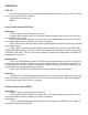
Initial Settings When first placing the system in service, the hold-on time should be set to an initial value. Three to five hours is suggested as a starting point. If the heaters turn off before the snow is completely cleared and the melt water evaporated, increase the hold-on time by an hour or two. If the heaters operate for several hours after the pavement is clear and dry, decrease the hold-on time by an hour. Continue this process until satisfactory performance is achieved.
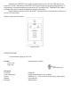
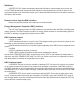
Figure 2: SCP-120 front panel detail RCO Remote Control Unit The RCO Remote Control Unit is used with the SCP-120. It adds remote control and status display to the SCP-120 control at a location convenient to personnel capable of observing snow melting system operation. Snow, slush or ice, either alone or in combination, must contact at least one sensor to start melting. Heater operation continues until all sensors are dry.
Operating the HEATER CYCLE switch operates heaters for the CYCLE TIME which is normally set to 2 hours. Operating the HEATER CYCLE switch during the cycle time stops the timer. If the pavement or ambient temperature exceeds the SCP-120 HIGH LIMIT TEMPERATURE setting, the heater duty cycle is reduced or disabled to prevent overheating. Status indicators include SUPPLY and HEAT. These perform the same functions as those on the SCP-120 front panel. Figure 5 shows the RCO layout.
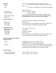
Control Supply Load Contact type Maximum Ratings Heater hold-on timer System test SCP-120: ETI PN 22470: 120 VAC, 50/60 Hz, 35 VA SCP-120: ETI PN 22470: 120 VAC, 24 amp max. inductive ETI PN 22471: 208-240 VAC, 24 amp max. inductive SCP-120: Form C SCP-120: Voltage: 120VAC Current: 24 amps 0 to 10 hours; actuated by snow stopping or toggle switch Switch toggles the heater contact on and off. If temperature exceeds high limit, heater cycles to prevent damage.
OPERATION SCP-120 The snow melting system can be monitored and controlled either locally from the SCP-120 itself or from two remote locations including: • RCO Remote Control Unit • BEMC Local Control from the SCP-120 Indicators: • SUPPLY (green) shows that power is present. • SNOW (yellow) shows that there is a snow/ice signal originating from at least one of the sensors attached to the system. • HEAT (yellow) shows that there is a call for heat.
Switches: • HEATER CYCLE switch momentarily depressed will start a manual heater cycle for the set CYCLE TIME. Momentarily depressed while heaters are being operated by a hold-on timer or during manual heater cycle will end the heater cycle. Heater operation during snow conditions cannot be canceled in this manner. Remote Control from the EMC Interface Please see the EMC section of the manual for interface details.
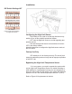
Installation DIP Switch Settings HLT GF disabled Figure 8: DIP Switch Setting for High Limit Sensor Configuring the High Limit Sensor Dip Switch pin 3 is used to set the high limit sensor operation to one of two possible operational modes: • OFF sets the high limit sensor as a slab regulating temperature sensor. • ON sets the high limit sensor as an ambient air sensor. OFF is the factory default. Index 8 shows how to configure the high limit sensor mode at the DIP switch.
Supply Figure 10: 120 VAC SCP-120 Operating two electrically held contactors
22 21 20 19 18 17 16 15 14 13 12 11 10 9 8 7 6 5 4 3 2 1 Figure 16: SCP-120 & RCO remote connection
Black White 22 21 20 19 18 17 16 15 14 13 12 11 10 9 8 7 6 5 4 3 2 1 Figure 19: SCP-120 Sensor Connections White Red Red Black AIR-SS
Figure 20: SCP-120 EMC connections
Figure 21: SCP-120 Electrician’s DVM
Figure 22: SCP-120 (Slab or Ambient High Limit Sensor) 95-107 ohms (on 200k scale of ohms meter) Thermistor connections
Contactor Connections Contactor Number Connection 1 2 3 4 5 6 7 8 9 10 11 12 13 14 15 16 17 18 19 20 21 22 Sensor Connection (White Wire) Sensor Connection (Black Wire) Sensor Connection (Red wire) Satellite Panel Connection Satellite Panel Connection Satellite Panel Connection Satellite Panel Connection RCO Connection RCO Connection Thermistor Connection Thermistor Connection Electrician’s DVM Electrician’s DVM Output Common Heat Snow Alarm Supply High Temperature Limit Override On Override Off Close Ov
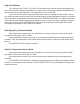
APS-3C AUTOMATIC CONTROLLER WIRING TO RELAY (120V) APS-3C Automatic Snow Controller (120V) Neutral Hot Leg Neutral 120V 15 Amp Breaker LNR (Relay Panel) with 2-Pole relays (120V Coils) L Hot (L1) Inputs for 120V N 24/7 Installation Support • Lifetime Technical Assistance • Free Design Service • www.WarmlyYours.
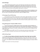
APS-3C AUTOMATIC CONTROLLER WIRING TO SENSORS & RCU (CLASS 2 CONNECTIONS) Optional Device 21 20 19 18 17 16 15 14 13 12 11 10 9 8 7 6 5 4 3 Black White RCU-3 Unit Red Thermistor probe type sensor (mounts in metal conduit within the slab between two passes of heater cable) CIT-1 Aerial Snow Sensor 2 1 APS-3C Automatic Controller Panel 10272-A 1/11 24/7 Installation Support • Lifetime Technical Assistance • Free Design Service • www.WarmlyYours.