
Installation Guide
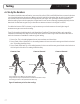
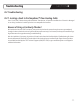
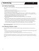
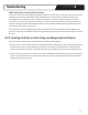
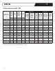
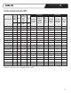

Figure 9. Attachment points for ohm readings
Testing
SECTION 6
6.4 Go by the Numbers
Theresistanceshouldbemeasuredfromtheinnercoreoftheyellow(120V)orred(240V)leadwireatoneendtotheinner
coreoftheblackleadwireattheotherend.Makesurethattheprobeoftheohmmeterdoesnottouchthetinnedsheath
wireateitherend.Donotholdthewiresontotheprobeswithyourngers.Evenyourbody’selectricalresistancecan
affectthereadingifyoutouchthemeterpoles.Adigitalmeteriseasiertouseandstronglyrecommended.Verifythatthe
batteriesoftheohmmeteraregood.Setyourohmmetertomeasureresistanceintherangeof0to200Ω.
Forcablesthathaveover200Ωresistance,itmaybenecessarytosettheohmmetertothenexthigherrangeof
measurementtogetanaccurateohmreading.
Three(3)ohmreadingsshouldbetakenforeachWarmlyYoursTempZone™FloorHeatingCableateachstageofthe
installationandrecordedinthetableonthewarrantycardinsection10.RefertoFigure9forinstructionsabouthowto
attachtheohmmeterorPowerMan™totakeeachtypeofreading.
1.CoretoCore:Thisisthereadingbetweenthetwoinnerconductorsontheleadwires.
2.CoretoSheath,Yellow/RedLead:Thisisthereadingbetweentheinnercoreandtheoutergroundsheathonthelead
wire.Thisreadingshouldbeinnity.
3.CoretoSheath,BlackLead:Thisisthereadingbetweentheinnercoreandtheoutergroundsheathontheleadwireat
thenishpointofthecable.Thisreadingshouldbeinnity.
Yellow
or Red
Ground
Ground
Yellow
or Red
Black
Black
Yellow
or Red
Ground
Ground
Yellow
or Red
Black
Black
Yellow
or Red
Ground
Ground
Yellow
or Red
Black
Black
Core to Core Core to Ground Core to Ground
The ground wire may differ from the images above.
The ground wire may be represented as a additional wire with a stripe.
The testing procedure is still performed the same way.
21