TW-F10BS-HP TW-F10PS-HP TW-F10KS-HP Installation & Operation Manual for WarmlyYours Infinity Dual Connection Towel Warmers
Thank you for choosing your finely crafted WarmlyYours Towel Warmer. Now you can add luxury and comfort to your bathroom with the soothing embrace of a warm towel or bathrobe upon stepping from the shower. The radiant heat from the Towel Warmer warms your towel. Included in this document are all necessary installation and operation instructions. If you encounter any difficulties while installing your system, installation support is available by phone at (800) 875-5285.
Affixing the Towel Warmer to the Wall Step 1 raw a diagram of the preferred location of the brackets on the D Towel Warmer box to create a template (see Step 2 for template instructions). At least two of the four brackets must be attached directly to a stud. The Infinity Plug-In model must be installed less than 6 feet (183cm) from a properly grounded outlet to ensure the plug can reach. Make sure to measure the distance from where the plug is attached to the towel warmer to the electrical outlet.
Affixing the Towel Warmer to the Wall - cont’d Note: Dimensions shown are distances between the center of anchor points. This example shows 16” on center construction. Your situation may vary depending on your stud spacing. WARNING: Locations of anchor points may vary. Measure all dimensions prior to rough-in and installation.
Affixing the Towel Warmer to the Wall (continued) Diagram B: Rough-In Diagram Note: Dimensions shown are distances between the center of anchor points. This example shows 16 inches on center construction. Your situation may vary depending on stud spacing. WARNING: Locations of anchor points may vary. Measure all dimensions prior to rough-in and installation.
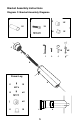
Bracket Assembly Instructions Diagram C: Bracket Assembly Diagrams A A A B A B B B 3X C 3X H 1X C A C g 3X g g gg I C C Power Leg h E d J 4X K 1X fedf e ggfe hh g f f h g h h A A B 4X ed e g d 1X D d d 4X f d B B C L C C C C B 3X C B B AC C A A 5 A B A B B g h h
Bracket Assembly Instructions (continued) B C C CC Parts List C C B e A f C C h B B B g A A B d Power Leg B B A K C M g C A H A C g Plug E g g Cd I d d ded e e fe e f fg f ghg gh h h L B C F B G d f g g e D K h J fd Infinity Power Leg h Part Number 0005-58180-0000 0005-58120-0002 0005-58140-0002 0005-58300-0000 B BB 0005-58110-0000 0005-58200-0001 0005-58200-0002 0005-58500-0000 0005-58200-0001 0005-58110-0000 0005-51900-0001 0005-58880-0000 0005-58810-
Installation Instructions (Plug-in) L 7
Installation Instructions (Plug-in) L 8
Bracket Assembly Instructions (continued) Plug-In Model Only Plug the cord into a properly grounded outlet. Do NOT use an extension cord to make the connection between the towel warmer plug and outlet. Step 1 Hold the towel warmer in place while tightening the hex-head screws D at the base of each section of tubing A using the smaller Allen wrench L provided to secure the towel warmer in place.
Bracket Assembly Instructions (continued) Step 3 Measure for bracket positions using the template if desired. At least two brackets must be attached to a stud. Step 4 Affix brackets C and H to the wall using screw G and drywall anchor F where necessary. Repeat Step 4 for the remaining brackets. Step 5 Place and orient the legs A and M with the threaded inserts located at four points on the back of the towel warmer.
Hardwire Assembly and Wiring (Diagram E) stepstep step 2 12 stepstep 1 1 step step 3.1 step 46 step step 6 3.1 step 3.1 stepstep 4 4 Φ8mm Φ8mm Φ8mm step step 12 21 stepstep stepstep 5 5 stepstep 2 2step 5 stepstep 7 7 step 3.2 step step 4 68 4 6 stepstep step step 46 4 step step step 79 97 stepstep step 10 stepstep 9 9 stepstep 11 11 stepstep 11 11 stepstep 12 12 step 12 step stepstep 9 79 stepstep 12 12 step 5 step step step 795 7 stepstep 10 10 step 11 stepstep 3.2 3.
Electrical Considerations Diagram F: Wiring Diagram (hardwired models only) WIRING DIAGRAM FOR TOWEL WARMERS WITH HARDWIRED TIMERS OR SWITCHES (GK16-30090-0001, GK16-30090-0003, GK16-30090-0002) NEUTRAL (WHITE) HOT (BLACK) LOAD (RED) GROUND (GREEN) TOWEL WARMER 3-WAY TERMINAL* (YELLOW/RED) POWER SOURCE 120VAC CONNECT TO HOUSE GROUND NEUTRAL (WHITE) CONNECT TO HOUSE GROUND ENSURE THE SYSTEM IS GROUNDED * - WE RECOMMEND TO ISOLATE THE YELLOW 3-WAY WIRE FROM THE OTHER WIRES USING A SOLDERLESS WIRE-N
OPERATION Manual Use the ON/OFF switch located on the bottom right side (when facing the towel warmer) to control when you want the unit to warm. Refer to Diagram D for switch for location. With a Control You may want to pair your towel warmer with a compatible WarmlyYours timer or switch. Make sure to refer to the installation manual of the control for proper operation and installation. If you have any questions, call 800-875-5285.
Product Construction - Towel Warmer The towel warmer is constructed from 304 stainless steel with a wall thickness of between 0.6 mm and 1.0 mm. The towel warmer is heated by a UL listed wire. The mounting brackets are manufactured from stainless steel and finished to match the finish of the specific model. Connection Method The heating wire is connected to a non-heated lead by a mechanical crimp connection, sealed with a heat shrink tube. Electricity is fed into the Towel Warmer via a Power Leg.
WarmlyYours Towel Warmer Warranty WarmlyYours.com Inc. warrants the WarmlyYours towel warmers (“the Product”) to be free from defects in materials and workmanship for two years from the date of sale, provided that the Product is installed in accordance with the accompanying Installation and Operation Manual and any special written design or installation guidelines provided by WarmlyYours.com Inc.