WARN INDUSTRIES, INC. Installation and Specification Guide for the 2.5ci ATV Winch Multi-Mount English ..................................................................... ...1 WARN INDUSTRIES, INC.* 12900 CAPPS ROAD * CLACKAMAS, OREGON 97015 (503)722-1200 * CUSTOMER SERVICE LINE 1-800-543-WARN * FAX (503)722-3000 PN 65405 A1 Français .................................................................... ..9 Español ...................................................................
Specifications As you read these instructions, you will see WARNINGS and CAUTIONS. Each message has a specific purpose. WARNINGS and CAUTIONS identify the hazard, indicate how to avoid the hazard, and advise of the probable consequence of not avoiding the hazard. PLEASE WORK SAFELY! Part number: PN 64500 (CE version: PN 64501) Rated line pull: 2500 lbs. (1134 kgs.
Step One: Safety First! Step Two: Winch Mounting When installing your ATV winch system, read and follow all mounting and safety instructions. Always use caution when working with electricity and remember to verify that no exposed electrical connections exist before energizing your winch circuit. Attach the roller fairlead to the multi-mount plate, use the provided: • 3/8-16 x 3/4 in., hex bolts • 3/8 in. lock washers. • 3/8 in. hex nuts.
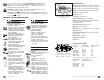
Step Four: Remote Socket Installation WARNING! TO PREVENT SERIOUS INJURY OR DEATH FROM EXPLOSION: • Do not drill into gas tank. • Verify the area is clear behind the mounting location before drilling. 10-24 hex nut & lockwasher Blue (6 ga.) Yellow (6 ga.) Black (6 ga.) 1/4in. (6.4 mm) diameter, 2 places 7/8in. (44.5mm) Blue (6 ga.) Keyway must point down Green Red (20 ga.) Black 7/8in. (22.2mm) diameter 1-3/4in. (44.5mm) 10-24 hex nut & hex head capscrew Not to scale.
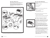
• Attach the 36 in. (0.9m), 6 ga. red wire to the positive red contactor post and battery (shrink wrapped end to battery). Attach the 36 in. (0.9m), 6 ga. black wire to the black contactor post and battery. • When possible, route the winch kit power (red) and ground (black) wires along the ATV’s existing wire routing paths under the seat and battery location areas. Ensure the wiring is not pinched when the seat is reinstalled. • Attach the contactor to the predetermined position on the ATV.
Caractéristiques Les directives suivantes comprennent des indications intitulées AVERTISSEMENT et ATTENTION. Chacune a un objectif bien précis : AVERTISSEMENT et ATTENTION identifient un danger, indiquent comment l’éviter et montrent ses conséquences possibles si on l’ignore. TRAVAILLEZ PRUDEMMENT ! Numéro de pièce : réf. 64500 (version CE : réf. 64501) Effort en 1ère couche : 1134 kg (2500 lb) sur un brin Moteur : Aimant permanent 12 V c.c.
Première Etape - La Sécurité Avant Tout! Deuxième Etape - Montage du Treuil Lisez et suivez les instructions de montage et de sécurité lors de l’installation du système de treuil VTT. Soyez toujours prudent(e) lorsque vous travaillez avec l’électricité et n’oubliez pas de vous assurer qu’aucune connexion électrique n’est exposée avant de mettre le circuit du treuil sous tension. Fixez le guide-câble à rouleaux sur la plaque de montage.
Quatrième Etape - Installation de la Prise de Télécommande AVERTISSEMENT! POUR ÉVITER LES RISQUES DE BLESSURES GRAVES OU DE MORT SUITE À UNE EXPLOSION : • Ne percez pas le réservoir à essence. • Assurez-vous qu’aucun objet ne se trouve derrière l’emplacement de montage avant de percer.
• Fixez le fil rouge de 0,9 m (36 po), cal. 6, sur la borne positive rouge du contacteur et la batterie (l'extrémité sous plastique sur la batterie). Fixez le fil noir cal. 6 de 0,9 m (36 po) à la borne noire du contacteur et à la batterie. • Dans la mesure du possible, faites passer les fils d'alimentation (rouge) et de masse (noir) du kit du treuil le long des chemins d'acheminement de fils présents du VTT, dans les zones situées sous le siège et autour de la batterie.
Conforme vaya leyendo estas instrucciones, se encontrará con mensajes de ADVERTENCIA y PRECAUCIÓN. Cada mensaje tiene un objetivo concreto. Las PRECAUCIONES y ADVERTENCIAS identifican el peligro, le indican cómo evitarlo, y le advierten de las consecuencias probables que conlleva no evitar dicho peligro.
Paso Uno: ¡la Seguridad es lo Más Importante! Paso Dos: Montaje del Cabrestante Cuando instale su sistema de cabrestante para vehículo todoterreno, lea y siga todas las instrucciones de montaje y de seguridad. Sea precavido siempre que vaya a trabajar con electricidad y no olvide verificar que no haya conexiones eléctricas desnudas antes de activar el circuito de su cabrestante.
Paso Cuatro: Instalación del Tomacorriente Remoto ADVERTENCIA PARA PREVENIR LESIONES GRAVES O ACCIDENTES MORTALES POR EXPLOSIÓN: • No perfore el tanque de la gasolina. • Compruebe que quede libre el área posterior a la ubicación de montaje antes de perforar.
• • • • Acople el cable rojo de 36 pulgadas (0,9 m) de calibre 6 al borne rojo positivo del contactor y a la batería (consolide el extremo envuelto en la batería). Acople el cable negro de 36 pulgadas (0,9 m) de calibre 6 al borne negro del contactor y a la batería. Cuando sea posible, pase los cables de corriente del kit del cabrestante (rojo) y de conexión a tierra (negro) por los pasos de cableado existentes del todoterreno situados debajo del asiento y donde se encuentra ubicada la batería.
© 2005 Copyright Warn Industries, Inc. All rights reserved.