
Instruction Manual


PAGE 11 85366 Rev. A0
Wiring Instructions-continued
Switch Instructions
Refer to instructions enclosed with ―GE Drum Switch CR102A1 diagram for wiring schematics. A copy of
those instructions and diagrams are inserted below for reference. Always defer to the actual diagrams that
are on the winch motor and in the Drum Switch.
Caution: Before installing in a nuclear
application, determine that the product is intended
for such use.
Warning : Disconnect power before installing or
servicing.
Installation:
1. Mount the switch to a flat surface.
2. Connect the switch in accordance with the
wiring diagram provided in the instructions or
in the cover of the switch.
Note: Motor branch circuit protection should be
provided in accordance with the national electrical
code and local codes or ordinances.
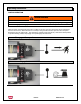
Convertibility (Maintained to
Momentary)
To convert the CR102A1 drum switch or similar
switches from “Maintained Contact” to “ Spring
Return to OFF”, remove the operating knob (6)
from the hub(7) by turning in a counter clockwise
motion. Pry the hub from the shaft. Turn the
handle 180 degrees and replace the handle, knob
and the hub to the switch.
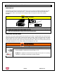
Mechanism Assembly
To disassemble the switch, remove the handle, hub
cover plate and stationary contacts. Remove the
two screws holding the case top and then lift off the
case top. Rotor assembly can then be removed.
Caution: Roller (3) is spring loaded and is loose
in arm (4). Caution must be exerted not to loose
the roller. Remove the roller from arm (4). To
reassemble, place the roller in the arm (4). Place
the rotor in the case by engaging the roller(3) with
the cam and inserting the shaft in the hole at the
bottom of the case. Reassemble by reversing the
above procedure
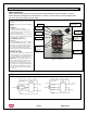
Figure 1. CR102A1
Wiring Diagram for 3000ACI and CR102A1
(2) Rotor
Assembly
(1)
Stationary
Contacts &
Support
(2) Rotor
Assembly
(6) Operating
Handle & Knob
(5) Spring
(4) Arm
(3) Roller
(7) Hub
(1)
Stationary
Contacts &
Support