
Owners manual


8 9
WARN Industrial Winches
WARN Industrial Winches
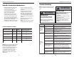
Hydraulic Winches: general information
NOTE: The hydraulic system diagram and
component descriptions are provided for general
reference. Consult a knowledgeable hydraulics
representative for specific recommendations on
component selection, interconnection, layout,
and best practice.
The pressure rating of the winch motor is
determined by (a) the maximum allowable
pressure at the motor inlet port and (b) the
maximum allowable pressure drop across the
motor. Pressure drop is defined as the difference
between the inlet pressure (P1) and the outlet
pressure (P2) at the winch motor. Exceeding the
maximum inlet pressure may damage the motor.
Exceeding the maximum pressure drop may
cause failure of winch components.
HYDRAULIC FLUID: The hydraulic fluid used
with the winch must be an extreme pressure,
anti-wear hydraulic oil with oxidation and
corrosion inhibitors. It must contain a foam
suppressant, and have a viscosity rating of 100-
300 SSU at 15-45 °C.
WARNING
Failure to observe these instructions could
lead to property damage, severe injury, or
death
• Never exceed the maximum recommended
hydraulic pressure or flow for any of the
components used.
• Always use a tandem-center type control
valve ( A & B work ports blocked) to insure
proper brake operation.
• Always make sure all hydraulic system
components are functioning correctly.
• Never use a standard motor valve.
Typical hydraulic system components
10
3
2
4
7
6
5
9
P1
P2
8
1
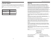
Connections for series wound DC motors (3 terminals)
Connections for permanent-magnet DC motors (2 terminals)
Battery
+
_
Controller Cover
green
white
black
#1
#1
+
#2
#2
_
Controller
Permanent
magnet motor
Controller cover
Controller
A
F1
F2
Series wound motor
A
F1
F2
Thermal switch
wires from bottom
of motor cut in here
X
green
white
black
Battery
+
_
+