2 Volt Utility Controller for 4, 6, or 8 Brakes No.
Contents Introduction . . . . . . . . . . . . . . . . . . . . . . . . . . . . 2 Installation . . . . . . . . . . . . . . . . . . . . . . . . . . . . . 3 Mounting Under Instrument Panel . . . . . . . . . . . 3 Hydraulic Connection . . . . . . . . . . . . . . . . . . . . . 3 Electrical Connection . . . . . . . . . . . . . . . . . . . . . 5 Sensitivity Adjustment . . . . . . . . . . . . . . . . . . . . 6 Optional Equipment . . . . . . . . . . . . . . . . . . . . . . 7 Warranty . . . . . . . . . . . . . . . . .
Mounting Holes Installation These instructions provide for ease of installation. Please follow them carefully. The basic installation steps are: 1. Mount the controller inside the towing vehicle. 2. Connect the controller into the towing vehicle’s hydraulic system. 3. Connect the controller electrically. 4. Adjust the controller for synchronized braking. Mounting Under Instrument Panel 1.
2. On towing vehicles with dual brake systems (built since 1966) the controller must be connected to the rear brake portions of the system. Note: The rear portion of a master cylinder does not always control the rear brakes. Trace the hydraulic tubing to be sure connections are made in the rear brake system. 3. Controller Installation in Series Type Power Brake System.
4. Remove a knock-out plug or cut a hole in the firewall near the mounted controller. 5. Cut the wire to a proper length for reaching the controller. Strip the wire and feed it through the firewall hole. 6. Connect this wire to the blue brake lead wire extending from the back of the controller. Figure 6 9. To test for sponginess and leaks, pump the brake pedal and hold it depressed for approximately one minute. If sponginess exists, the entire system should be bled at the wheel cylinders.
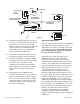
SOCKET TO STOPLIGHT LOAD CONTROL 1300-78 OPTIONAL BLUE UTILITY CONTROLLER MOUNTED ON DASH STARTER 10 GAUGE WIRE RECOMMENDED BLACK 10 GAUGE WIRE RECOMMENDED RED MECHANICAL STOPLIGHT SIGNAL FUSE STOPLIGHT SWITCH BATTERY Figure 7 10. The black or power lead of the controller is last to be connected. Enough hook-up wire should remain to make this connection. Strip one end of this hook-up wire and feed it through a hole in the firewall from the engine side.
Optional Equipment When the trailer load is variable or less than trailer brake capacity, a Warner Electric Load Control, part no. 1300-78 should be added in series with the brake circuit. The Load Control provides the capability to properly proportion the braking power of the trailer brakes to the trailer weight. The Load Control is connected into the trailer brake wire connected to the blue lead from the controller. Its position is shown in the wiring diagram under “Electrical Connection.
Warranty Warner Electric LLC warrants that it will repair or replace (whichever it deems advisable) any product manufactured and sold by it which proves to be defective in material or workmanship within a period of one (1) year from the date of original purchase for consumer, commercial or industrial use. This warranty extends only to the original purchaser and is not transferable or assignable without Warner Electric LLC’s prior consent. Warranty service can be obtained in the U.S.A.