CBC-1500AHFC & 1550AHFC Closed Loop Unidirectional Clutch/Brake Control System P-291 819-9050 Installation Instructions To prevent personal injury, ensure all personnel are clear of conveyor line and the pusher before performing any adjustments on the control.
Contents Introduction . . . . . . . . . . . . . . . . . . . . . . . . . . . . 2 Ordering Information . . . . . . . . . . . . . . . . . . . . . 3 Specifications . . . . . . . . . . . . . . . . . . . . . . . . . . . 3 Installation . . . . . . . . . . . . . . . . . . . . . . . . . . . . . 3 Connection Diagram CBC-1500 . . . . . . . . . . . . 4 Control Adjustments. . . . . . . . . . . . . . . . . . . . . . 4 Connection Diagram CBC-1550 . . . . . . . . . . . . 5 CBC-1000AH Operation. . . . . . . . . . . . . . .
Ordering Information Model Number CBC-1550AHFC Control CBC-1500AHFC Control Encoder Cable (Accessory) 600 Pulse Per Revolution Encoder with Marker Pulse & 10' Cable RS-232 to RS-422/485 Converter (Accessory) Part Number 6050-448-008 6050-448-006 6060-101-003 6060-101-061 6060-101-232 Specifications Input: CBC-1500AHFC-90: 120 VAC ±10%, 50/60 Hz, 1 Phase, 300 VA max. CBC-1000AH: Switch selectable AC power input to be 120 VAC only. CBC-1550AHFC-24: 220 VAC ±10%, 50/60 Hz, 1 Phase, 300 VA max.
Connection Diagram CBC-1500AHFC Back side of cover CONTROL OUTPUTS RXD RXD + TXD TXD + +12v SIG A SIG B COM START STOP MARKER/SIG Z RESET COM START EARLY WARNING BRAKE ON ZERO SPEED ZERO SPEED + DELAY 1 ZERO SPEED + DELAY 2 AUX START BATCH COMPLETE HOT NEUTRAL 120 BLD. GND.
Connection Diagram CBC-1550 Back side of cover CONTROL OUTPUTS RXD RXD + TXD TXD + +12v SIG A SIG B COM START STOP MARKER/SIG Z RESET COM START EARLY WARNING BRAKE ON ZERO SPEED ZERO SPEED + DELAY 1 ZERO SPEED + DELAY 2 AUX START BATCH COMPLETE HOT NEUTRAL BLD. GND.
CBC-1000AH Control Operation Successful operation will require knowledge of the following definitions and their relationships to the Timing Diagram below. Function Key Definitions Count 1 COUNT Move Preset 2 MOV PST Early Warning 3 E.W. Batch* 6 BATCH Batch Preset* 7 BCH PST Braking Distance 8 BRK DIS The actual move distance, in pulses or scaled into engineering units (inches, feet, rotations, degrees, etc.), displayed dynamically.
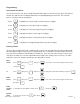
Programming View Presets and Values The six function keys may all be viewed during the RUN mode. To view their values, press the desired function key and the value is displayed with the corresponding display annunciator. The controller process continues without interruption. 1 Press COUNT Press MOV PST Press E.W. Press BATCH Press BCH PST Press BRK DIS to display the current length or position (up to six digits). 2 to display the move preset (up to six digits).
Six Simple Setup Steps: After encoder, clutch/brake, and power connections are made per one of the connection diagrams found on pages 4 and 5: 4. Press the RUN/PGM key to get back to RUN Mode and out of Program Mode. Enter in the Move Preset (MOV PST) value, key 2 (refer to page 6 for instructions on Entering presets). Due to the auto-home feature, the Move Preset must be equal to one revolution of the encoder (600 pulses). The display can be scaled to display any engineering units. 1.
Programming Line 1 2 3 4 5 6 7 8 9 10 11 12 13 14 15 16 17 18 19 20 Display h. bd. bd.AuE. cc. dP. FrSt. PLoc. CrEt. ArSt. ol. o2. o3. o4. o5. o6. o8. dl. d2. 05P.
Programming Line 1 The number that is downloaded to the display when the marker pulse is detected. 2 The first brake distance used by the CBC-1000 at power-up. 3 The number of cycles used for the running average of brake distance. 4 The scaling factor for the front panel display (0.5000 for display in pulses). 5 Number of decimal points displayed. Affects all distance values in other registers. 6 Enables or disables front panel reset in the Run Mode.
CBC-1500AHFC and CBC-1550AHFC Program for Fast Cycling Feature Line 1 2 3 4 5 6 7 8 9 10 11 12 13 14 15 16 17 18 19 20 21 22 23 24 25 26 27 28 29 30 31 32 33 34 35 Program 275 25 3 0.5 OFF ON OFF OFF ON 0.1 0.01 0.1 0.07 0.05 0.05 LATCH 0.1 0.01 0.05 -.-.-.-.-.-. -.-.-.-.-.-. -.-.-.-.-.-. -.-.-.-.-.-.
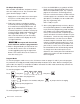
CBC1500AHFC and CBC1550AHFC Normal Cycle: A) Brake is engaged. B) The CBC1500AHFC receives a “start input’ from external control. C) The CBC1500AHFC sends a “start output” that turns on the clutch. D) The encoder starts rotating and display starts counting positive numbers. If display counts negative numbers, swap encoder inputs Sig. A and Sig. B. E) The CBC1500AHFC receives an “encoder index mark” and matches the “CBC1000 count” with the system count (CBC1500AHFC count).
Additional Features These features are available on the current unit, but some extra hardware or programming is needed to enable them. Batch Counter: This feature will trigger the Batch Complete output, pin 21, when the Batch Preset, key 7, reaches the Batch Counter, key 6, value (refer to Entering presets, page 6, to enter a value in the Batch Preset). The Batch Counter can be manually or automatically reset. Manual reset is the default setting in the program mode line 16 (08. latch).
CBC-1000 Diagnostic Tests t0: Keyboard Test: Tests the function of the front panel keys. Press to begin test. RUN: will be displayed. Press each front panel key except The display will indicate if the key is functional. t1: to test key. Non-Volatile RAM Test: Tests CBC-1000 RAM. Press t2: RUN PGM to begin test. The test will return PASS or FAIL. Press to continue. Input Test: Tests whether CBC-1000 is accepting inputs. Press to begin test. Activate inputs to control.
Troubleshooting Problem Machine starts but does not stop Solution Machine stops out of position • Establish a move Preset • Ensure brake functions properly using output test. • Make sure the marker pulse is detected before brake outputs fire. Display counts backwards • Reverse Encoder A, B, wiring. Machine stops abruptly, not a soft stop • Turn down torque adjust potentiometer for Channel 1. Machine stops but then restarts • Control may be responding to a start command. Check for transient signals.
Electrical Diagram CBC-1000AH TERMINAL 1 2 3 4 5 6 7 8 9 10 11 12 13 14 15 16 17 18 19 20 21 22 23 24 2 3 4 5 6 7 8 9 10 11 12 13 TB1 FUSE 1 P.C. BOARD ASSY. J4 1 2 3 4 5 6 J5 1 2 3 4 5 6 1 2 3 4 5 A/C FILTER EGND NEUT HOT RED BLACK N.C. J3 N.C. TB2 1 2 3 4 5 6 7 8 N.C.
Dimensional Diagram 1.00 5.43 NOTE 3 A .15 1.25 H1 H F C1 2.68 2.75 5.000 .935 .164ø 4 PLCS .910ø 1.250 F 3.200 E2 3.00 1.57 11.00 0.700 1.75 G1 ±.005 .500 Ø 2 PLCS 5.40 6.36 1.75 E3 D3 0.44 1.50 .218 Ø 4 PLCS NOTE 3 6.00 1.26 DS E1 E1 C1 NOTE 3 2 PLCS. A DS G G 3.62 .87 ø 2. PLCS G1 3.00 1.25 6.
Dimensional Diagram NOTE 3 (REF) 1.50 .25 .31 0.870 4.13 4.75 G1 10-32 WELD NUTS 4PLCS 10-32 TH'D TO BE FREE OF PAINT 4 PLCS 6.250 0.870 H J DRILL THRU ø0.136 THEN TAP 8-32 2 PLCS 8.250 8-32 TH'D TO BE FREE OF PAINT 2 PLCS 2.375 0.75 3.12 SECTION A-A D2 D4 1.) WELD NUTS 4 PLACES AS SHOWN OHIO NUT & BOLT CO. P/N WF 1405 OR EQUIV. 2.) ENCLOSURE TO BE 10X8X6 SIMILAR TO HOTTMAN P/N A-10086CH W/COLOR BLACK POLY POWDER COAT. 3.) ENLARGE FOUR MOUNTING SLOTS FROM .22X.28LG TO .25X.375LG.
CBC1500AHFC and CBC1550AHFC Revision B Installation Procedure To prevent personal injury, ensure all personnel are clear of conveyor line and the pusher before performing any adjustments on the control. Programming Adjustments 1. 2. Turn on the power switch of the control. The power switch should illuminate. On the control display, press #2 (MOV-PST). The number 600 should be displayed on the LED display.
25. 26. 27. 28. 29. 30. 31. 32. 33. 34. 35. 36. 37. 38. 39. 40. 41. 42. 43. 44. 45 46. 47. 48. 20 Press key 0. Press the arrow down key. If it is not 00.01: Press “RESET/CLEAR” Press key 1. Press the arrow down key. If it is not 00.20: Press “RESET/CLEAR: Press key 2. Press key 0. Press the arrow down key. If it is not 00.10: Press “RESET/CLEAR” Press key 1. Press key 0. Press the arrow down key. If it is not 00.05: Press “RESET/CLEAR” Press key 5. Press the arrow down key. If it is not 00.
This completes all the programming of the Warner Electric control. Common Terminology 1. 2. 3. 4. 5. 6. Home position. – Long arm is straight and both paddles are inside the pusher enclosure. Home reference. – Position of the pusher’s arm when the “ref” indicator on the display is illuminated. Move preset. – Number of pulses that the control is going to count in each cycle. For this application it is 600 pulses. Early Warning.
Warranty Warner Electric, Inc. warrants that it will repair or replace (whichever it deems advisable) any product manufactured and sold by it which proves to be defective in material or workmanship within a period of one (1) year from the date of original purchase for consumer, commercial or industrial use. This warranty extends only to the original purchaser and is not transferable or assignable without Warner Electric, Inc.’s prior consent. Warranty service can be obtained in the U.S.A.