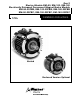
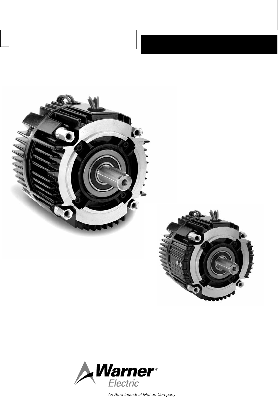
Gen 2 Electro-Module EM-50, EM-100, EM-180 Electrically Released Permanent Magnet Brake Module EM-50-20FBB, EM-100-20FBB, EM-180-20FBB EM-50-20FBC, EM-100-20FBC, EM-180-20FBC Installation Instructions P-273-5 819-0529 Vented Enclosed Version Optional
Contents Mounting a C-Faced Motor . . . . . . . . . . . . . . . .4 Bolting Two Modules Together . . . . . . . . . . . . .5 Adjusting Air-Gap . . . . . . . . . . . . . . . . . . . . . . .5 Mounting the Brake to a Motor . . . . . . . . . . . . .7 Installing the Motor Mount Bracket . . . . . . . . .7 Installing the Base Mount . . . . . . . . . . . . . . . . .7 Mounting to a Reducer . . . . . . . . . . . . . . . . . . .8 Mounting on the Input and Output Shafts . . . .8 Electrical Connections . . . . . . . . . .
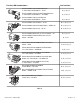
For these EM combinations: Use Sections: Electro-Module Clutch-Brake Between C-Face Motor and Reducer – 10-20 A, C, G, I, K Electro-Module Clutch-Fail Safe Brake Between C-Face Motor and Reducer – 10-20FBC A, J, G, I, K Electro-Module Clutch only Between C-Face Motor and Reducer – 10-40 A, C, G, I, K Electro-Module Clutch-Brake – 20-30 B, C, G, H, I, K Electro-Module Clutch-Fail Safe Brake – 20FBC-30 B, J, G, H, I, K Electro-Module Clutch only – 30-40 B, C, G, H, I, K Electro-Module Brake only
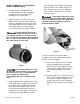
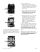
Section A: Mounting a C-Faced Motor (10-20, 10-20FBC, 10-40) 1. A hardened key is provided with the mounting hardware for the (10) Module. Insert this key onto the motor shaft (staking the key is necessary). 2. Align the keyway in the bore of the (10) Module to the key in the motor shaft and slide the (10) Module onto the motor shaft. The normal alignment of the module to the motor will be with the wire exit upright (12 O’Clock) position as shown in Figure 1.
Setscrews orientation should match. Secure the modules together with four (4) tie-bolts provided. Tighten the four (4) bolts alternately to ensure even alignment of the modules. Tighten them to 30-35 foot pounds.
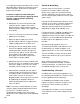
This is a three step process. 1. Simply slide the screwdriver through the window. By twisting the screwdriver, it works as a wedge to apply pressure on the back of the armature pushing it toward its mating friction surface. 2. Rotate the output of the unit. The rotor and window should stay in place when you do this. Only the armatures will move. If you rotate the input of the unit, the rotor and access window will rotate as well.
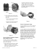
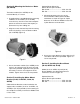
Section D: Mounting the Brake to a Motor (20, 20FBB) The brake module (20 or 20FBB) can be mounted directly to a motor. 1. A hardened key is provided with the mounting hardware for the module (20 or 20 FBB). Insert this key onto the motor shaft and prick punch the end of the motor shaft keyway to prevent the key from sliding out. Optional Motor Mount Kit, Warner Electric part numbers: EM-50/100................................5370-101-078 EM-180.....................................5370-101-079 1.
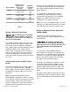
3. Bolt the (10-20, 10-20FBC, or 10-40) motor/module or output of a (20-30, 20FBC30, or 30-40) double shafted module to the reducer flange. The four (4) bolts that are required (3/8-16UNC2A) are typically provided with the reducer. Tighten to 18-22 foot pounds of torque. Section H: Mounting on the Input and Output Shafts Figure 10 1. The pilot diameters on each end of the Electro-Module will mate with the pilot diameters on the base. 2.
Distance Load is Applied from Electro-Module Housing Face "A" Inches EM-50 1" Center of Shaft 2" End of Shaft 3" EM-100 1” Center of Shaft 2” End of Shaft 3” EM-180 1" Center of Shaft 2" End of Shaft 3" Maximum Load Rating "R" Lbs. 177 123 95 192 134 104 192 134 104 Table 3 Switching of clutch and (FB) brake with this type of module should allow both clutch and brake to be engaged and disengaged simultaneously for proper operation.
The following procedure describes how to set the adjustable power supply to the optimum release point of the brake. A volt-meter is required to perform the procedure. No power is applied to motor during this procedure. Power normally supplied by motor to brake control should be supplied by alternate method. 1. With power off, connect the positive (red) lead of the power supply to the positive (black) lead of the brake and the negative lead of the power supply to the negative lead of the brake. 2.
• If power is present in the proper voltage and current, then skip ahead to the Mechanical Troubleshooting Section. Mechanical Data EM-50 Static Torque - lb. ft. • • • If power is not present, inspect the lead wires for breaks or cuts. 16 30 3600 3600 20 9.2 11.2 Maximum Speed - rpm Average Weight - lbs. If the wires are intact, the problem may be with the power supply or the switch.
Notes: Visit Warner Electric’s website at www. warnerelectric.com for dimensional drawings, weights, inertia’s and a complete offering of our products including clutches, brakes, and clutch or brake controls and service parts. In addition, Warner Electric module products, controls and service parts information can be found in our catalog P-1234-WE. Call 815-389-3771 to request any of our catalogs.
Warranty Warner Electric LLC warrants that it will repair or replace (whichever it deems advisable) any product manufactured and sold by it which proves to be defective in material or workmanship within a period of one (1) year from the date of original purchase for consumer, commercial or industrial use. This warranty extends only to the original purchaser and is not transferable or assignable without Warner Electric LLC’s prior consent. Warranty service can be obtained in the U.S.A.