
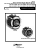
Owner's manual

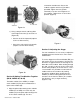
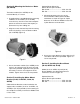


orientation should match. Secure the
modules together with four (4) tie-bolts
provided. Tighten the four (4) bolts
alternately to ensure even alignment of
the modules. Tighten them to 30-35 foot
pounds. (Figure 4)
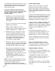
Section C: Adjusting the Airgap
For new installations it is necessary to adjust the
airgap between the friction faces of the clutch
and/or brake.
To set the airgap for an Electro-Module (EM) you
will need to access the armatures. You will note
that there are gaps between the housing fins on
both sides of the module. When looking through
this gap, you will see the fan on the clutch rotor.
On the outer periphery of the fan there is a 1/2 x
1 inch window. It is possible to look inside the
module and see the armatures by looking
through this window. When looking into the
window you will be looking between the two
armatures of the clutch or brake. [In a module
(10-40) there is only a single armature.]
(Figures 5 & 6)
5
Warner Electric • 800-825-9050 819-0529
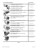
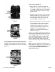
c) Using a torque wrench and long Allen
socket tighten the two (2) setscrews to:
(Figure 3b)
• Size 50: 80-85 inch pounds (requires
5/32 inch Allen wrench)
• Size 100 or 180: 40-45 inch pounds
(requires 1/8 inch Allen wrench)
Section B: Bolting Two Modules Together
(20-30, 20FBC-30, 30-40)
The brake module (20 or 20FBC) or output
clutch module (40) may be assembled to the
input clutch module (30).
1. Align the pilot and mounting holes of brake
module (20 or 20FB) or if clutch only the
module (40) to the pilot and mounting holes
of the clutch module (30). The wire
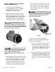
Figure 3a
Side Vent
Access Slots
Setscrews
Figure 3b
Figure 4