Primary Brakes PB-120, PB-170, PB-250, PB-400 P-201 819-0480 Installation Instructions
Contents Installation Instructions PB-120 PB-170 PB-250 PB-400 . . . . .2-9 Electrical Specifications . . . . . . . . . . . . . . . . . . . .5 Drawings and Parts Breakdown or Exploded Views PB-120 . . . . . . . . . . . . . . . . . . . . . . . . . .10-11 PB-170 . . . . . . . . . . . . . . . . . . . . . . . . . .12-13 PB-250 . . . . . . . . . . . . . . . . . . . . . . . . . .14-15 PB-400 . . . . . . . . . . . . . . . . . . . . . . . . . .16-17 Warranty . . . . . . . . . . . . . . . . . . . . . . .
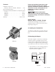
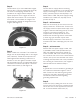
Figure 2 Figure 3 2. A machined pilot diameter is provided on the magnet mounting flange (refer to illustration drawings page 10-17) to aid in the proper positioning of the magnet. 3. An optional release spring may be used with the standard armatures and hubs. The release spring forces the armature back against the hub retainer ring when the magnet coil is de-energized. 3. Once the mounting surface has been prepared, the magnet is bolted in place with capscrews and lockwashers. (Figure 2.
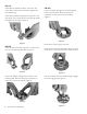
PB-170 Assemble the splined armature to the hub. The shiny side of the armature should be against the hub retainer ring. Assemble the release spring into the groove in the hub spline. The curved portion of the spring should be against the armature. (Figure 4) PB-400 Insert the release springs into the backing plate holes of the armature. Bow the springs as necessary to insert them into the armature. (Figure 7) Figure 7 Figure 4 PB-250 Remove the snap ring from the hub.
Assemble the snap ring into the groove in the hub, clamping the release spring against the end of the spline. (Figure 9) 4. Secure the assembly in this position by alternately tightening the two setscrews in the hub. D. Mounting the Armature Assembly 5. The hub will need to be repositioned as wear occurs with time. 1. (250 and 400 units only) Insert a key in the keyway of the shaft. 2. Slide the armature assembly onto the shaft. 3.
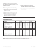
Installation Instructions Components 4 Conduit box kit No. 5200-101-010 contains all components needed to assemble a conduit box for PB400 brake. 12 10 When properly installed, this conduit box is designed to provide a proper means for field wiring terminations. It conforms to the requirements of Underwriters Laboratories. 8 11 Do not connect rigid conduit directly to the conduit box.
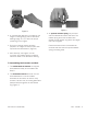
Step 2 Step 4 Fasten bracket (1) to clutch field/brake magnet with one No. 10-32 hex washer head screw (2). The screw is self-tapping, threads are not provided in the magnet bracket adapter. The square projection on the magnet fits into the square hole in the bracket. The curved side of the bracket mounts toward the magnet. The bracket flange is toward the flange side of the magnet. (See Figure 11) Connect electric supply cable to the fitting installed on the conduit box.
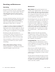
Burnishing and Maintenance Burnishing Maintenance Intimate metal to metal contact is essential between the armature and the metal rings (poles) of the magnet or rotor. Warner Electric clutches and brakes leave the factory with the friction material slightly undercut to assure good initial contact. Wear Pattern: Wear grooves appear on the armature and magnet surfaces. This is a normal wear condition, and does not impair functioning of the unit.
If the friction materials have been saturated with oil or grease, no amount of cleaning will be completely effective. Once such a unit has been placed back in service, heat will cause the oil to boil to the surface, resulting in further torque loss. Torque Loss: If a brake or clutch slips or loses torque completely, the initial check should be the input voltage to the magnet as follows: this manual. A very high or infinite resistance reading would indicate an open coil.
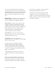
PB-120 Brake .312 For Bore sizes see chart below. .015 When New .062 .072 (Std.) .072 (Anti.) Std. Armature 12 .109 (Std.) .140 (Anti.) Antibacklash Armature .500 1.234 Max. Dia. Std. Arm. .375 Dia. Anti Arm. .562 Armature View #4-40 UNC-3A .072 (Std.) .072 (Anti.) 1.499/1.497 Pilot Diameter .343 .187 Max. .015 .625 .968 Max. 45° Bore Dimensions .130/.123 dia. (4) holes equally spaced on 1.312 diameter* 1.125 Max. Sq. Armature Bore Dia. .188/.187 .251/.250 (.313/.
PB-120 Brake Drawing I-25507 3 1B 1A-2 1A-1 2 1A Item 1A 1A-1 1A-2 1B 2 3 Description Armature and Hub Armature Hub 3/16" Bore 1/4" Bore Armature Antibacklash Armature 3/16" Bore 1/4" Bore 5/16" Bore Mounting Accessory Magnet 6 Volt 24 Volt 90 Volt Warner Electric • 800-825-9050 Part Number Qty. 1 5622-541-009 5622-541-008 110-0110 5622-111-004 5622-111-002 5622-111-003 5101-101-001 5373-631-003 5373-631-005 5373-631-007 1 1 How to Order: 1. Specify Type of Armature Desired. 2.
PB-170 Brake For Bore sizes see chart below. .390 .015 When New 12 Min. .086 (Std.) .094 (Anti.) Std. Armature .062 Antibacklash Armature .125 (Std.) .109 (Anti.) Armature View 1.718 Max. Dia. .625 Std. Arm. .752/.750 Pilot Dia. .843 Anti. Arm. 2.437/2.435 Pilot Diameter #8-32 UNC-3A .015 45° .515 .086 (Std.) .094 (Anti.) .437 Max. .812 1.375 Max. .204/.187 dia. (4) holes equally spaced on 2.125 diameter* Bore Dimensions Armature Bore Dia. .251/.250 .313/.312 .376/.375 1.812 Max. Sq.
PB-170 Brake Drawing I-25753 3 1A-3 1A 1A-2 1A-1 2 1B Item 1A 1A-1 1A-2 1A-3 1B 2 3 Description Armature and Hub Armature Hub 1/4" Bore 5/16" Bore 3/8" Bore Armature Release Spring Antibacklash Armature 1/4" Bore 5/16" Bore 3/8" Bore Mounting Accessory Magnet 6 Volt 24 Volt 90 Volt Warner Electric • 800-825-9050 Part Number Qty.
PB-250 Flange Mounted Brake For Bore & Keyway sizes see chart below. 1.250 .343 Max. 1.078 .015 When New .718 Std. Armature .171 (Std.) .187 (Anti.) Antibacklash Armature 1.187 2.625 Max. Dia. Std. Arm. K 1.063 1.061 Pilot Dia. 1.390 Anti. Arm. Armature View #8-32 UNC-3A .203 Min. .687 (Std.) .718 (Anti.) 24° .015 12° .437 Max. .062 1.968 (Std.) 1.984 (Anti.) .437 Max. .437 Max. Bore and Keyway Dimensions 2.625 Sq. 45° 3.500/3.498 Pilot Diameter .204/1.
PB-250 Flange Mounted Brake Drawing I-25519 2-1 1A-3 1A 2 1A-2 1A-1 3 1B Item 1A 1A-1 1A-2 1A-3 1B 2 2-1 3 Description Armature and Hub Armature Hub 3/8" Bore 1/2" Bore 5/8" Bore 3/4" Bore Release Spring Armature Antibacklash Armature 3/8" Bore 1/2" Bore 5/8" Bore 3/4" Bore Magnet 6 Volt 24 Volt 90 Volt Terminal Accessory Mounting Accessory Warner Electric • 800-825-9050 Part Number Qty.
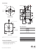
PB-400 Flange Mounted Brake 1.546 For Bore & Keyway sizes see chart below. .953 Std. Armature .015 When New Antibacklash Armature .328 Max. 3.562 Armature View Removable plug in ends for 1/2" conduit. Std. Arm. 1.250 4.234 Max. Dia. 3.750 Anti. Arm. 1.875 1.873 Pilot Dia. 1.640 1/4-20 UNC-3A .187 (Std.) .218 (Anti.) .343 4.687 Max. .875 (Std.) .843 (Anti.) .093 .015 1.312 .609 Max. 1.500 2.328 (Std.) 2.359 (Anti.) 4.250 Sq. 45° 5.625/5.623 Pilot diameter .296/.
PB-400 Flange Mounted Brake Drawing I-25694 3 1B 2-1 2 1A-2 1A 1A-3 1A-1 4 Item 1A 1A-1 1A-2 1A-3 1B 2 2-1 3 4 Description Armature and Hub Armature Hub 1/2" Bore 5/8" Bore 3/4" Bore 7/8" Bore Armature Release Spring Antibacklash Armature 1/2" Bore 5/8" Bore 3/4" Bore 7/8" Bore Magnet 6 Volt 24 Volt 90 Volt Terminal Accessory Conduit Box Mounting Accessory Warner Electric • 800-825-9050 Part Number Qty.
Warranty Warner Electric LLC warrants that it will repair or replace (whichever it deems advisable) any product manufactured and sold by it which proves to be defective in material or workmanship within a period of one (1) year from the date of original purchase for consumer, commercial or industrial use. This warranty extends only to the original purchaser and is not transferable or assignable without Warner Electric LLC’s prior consent. Warranty service can be obtained in the U.S.A.